2 rack mounting – PLANET FGSD-1008HPS User Manual
Page 24
User’s Manual of FGSD / FGSW Web Smart PoE Switch
24
Connection to the PoE Web Smart Switch requires UTP Category 5 network cabling with RJ45 tips. For
more information, please see the Cabling Specifications in Appendix A.
Step 5:
Supply power to the PoE Web Smart Switch.
Connect one end of the power cable to the PoE Web Smart Switch.
Connect the power plug of the power cable to a standard wall outlet.
When the PoE Web Smart Switch receives power, the Power LED should remain solid Green.
2.2.2 Rack Mounting
To install the PoE Web Smart Switch in a 19-inch standard rack, please follow the instructions described below.
Step 1:
Place the PoE Web Smart Switch on a hard flat surface, with the front panel positioned towards the front side.
Step 2:
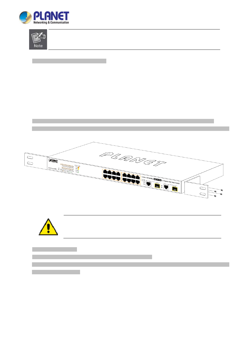
Attach the rack-mount bracket to each side of the PoE Web Smart Switch with supplied screws attached to the package.
Figure 2-5
shows how to attach brackets to one side of the PoE Web Smart Switch.
Figure 2-5
Attach Brackets to the PoE Web Smart Switch.
You must use the screws supplied with the mounting brackets. Damage caused to the parts by
using incorrect screws would invalidate the warranty.
Step 3:
Secure the brackets tightly.
Step 4:
Follow the same steps to attach the second bracket to the opposite side.
Step 5:
After the brackets are attached to the PoE Web Smart Switch, use suitable screws to securely attach the brackets to the
rack
,
as shown in
Figure 2-6
.