A.3 fiber optical cable connection parameter – PLANET IGT-902 User Manual
Page 64
User’s Manual of IGT-90x
-64-
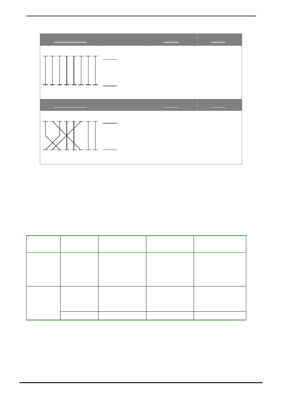
There are 8 wires on a standard UTP/STP cable and each wire is color-coded. The following shows the pin allocation
and color of straight cable and crossover cable connection:
Straight Cable
SIDE 1
SIDE2
SIDE 1
1
2
3
4
5
6
7
8
1
2
3
4
5
6
7
8
SIDE 2
1 = White / Orange
2 = Orange
3 = White / Green
4 = Blue
5 = White / Blue
6 = Green
7 = White / Brown
8 = Brown
1 = White / Orange
2 = Orange
3 = White / Green
4 = Blue
5 = White / Blue
6 = Green
7 = White / Brown
8 = Brown
Straight Cable
SIDE 1
SIDE2
SIDE 1
1
2
3
4
5
6
7
8
1
2
3
4
5
6
7
8
SIDE 2
1 = White / Orange
2 = Orange
3 = White / Green
4 = Blue
5 = White / Blue
6 = Green
7 = White / Brown
8 = Brown
1 = White / Orange
2 = Green
3 = White / Orange
4 = Blue
5 = White / Blue
6 = Orange
7 = White / Brown
8 = Brown
Figure A-1:
Straight-Through and Crossover Cable
Please make sure your connected cables are with same pin assignment and color as above picture before deploying the
cables into your network.
A.3 Fiber Optical Cable Connection Parameter
The wiring details are as below:
■
Fiber Optical patch Cables:
Standard
Fiber
Diameter (micron)
Modal Bandwidth
(MHz * km)
Max. Distance
(meters)
1000Base-SX Multi-mode
62.5
62.5
50
50
100
200
400
500
220
275
500
550
Multi-mode 62.5
50
50
5
4
5
550
1000Base-LX
Single-mode 9
N/A
5000*
2080-AA1130-004