Installation – ProSoft Technology AN-X-AMX User Manual
Page 9
AN-X-AMXRIO Page
5
Installation
Prevent Electrostatic Discharge
The module is sensitive to electrostatic discharge.
WARNING!
Electrostatic discharge can damage integrated circuits or semiconductors. Follow
these guidelines when you handle the module:
• Touch a grounded object to discharge static potential
• Do not touch the connector pins
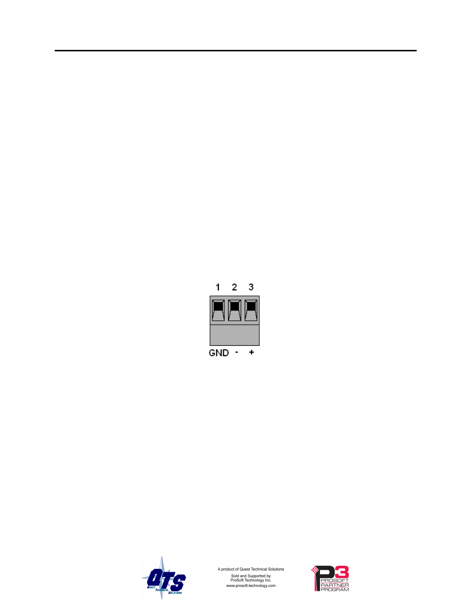
Power
AN-X requires a DC power input of anywhere from 12 to 24 VDC.
Left to right the pins on the power connector are chassis ground, negative voltage and
positive voltage.
The chassis ground should be connected.
Power consumption internally is 300 mA @ 12VDC or 150 mA @ 24VDC.
The part number for the power connector is Phoenix MSTB 2.5/3-ST-5.08
Cabling and Termination
Use a standard drop cable and passive tap M/N 57C380 to connect the module to the
coaxial network cable. The drop cable is a multi-conductor cable with 9-pin D-shell
connectors at each end. Connect one end to the connector on the module and the other
end to the passive tap.
The passive tap has two BNC connectors for connection to the coaxial cables and
terminating loads.
The network coaxial cable must be terminated with 75 ohm terminating loads attached to
the taps at the physical ends of the network. There should be two and only two
terminators on the network.