Cyclic redundancy check calculation timing – Altera MAX 10 FPGA User Manual
Page 25
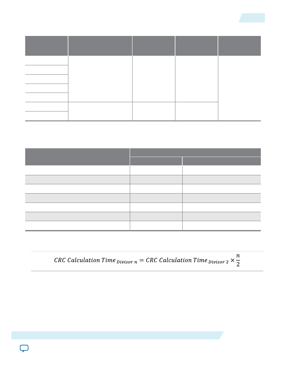
Table 2-17: Minimum and Maximum Error Detection Frequencies for MAX 10 Devices—Preliminary
Device
Error Detection Frequency
Maximum Error
Detection
Frequency (MHz)
Minimum Error
Detection
Frequency (kHz)
Valid Values for n
10M02
55 MHz/2
n
to 116 MHz/2
n
58
214.8
2, 3, 4, 5, 6, 7, 8
10M04
10M08
10M16
10M25
10M40
35 MHz/2
n
to 77 MHz/2
n
38.5
136.7
10M50
Cyclic Redundancy Check Calculation Timing
Table 2-18: Cyclic Redundancy Check Calculation Time for MAX 10 Devices—Preliminary
Device
Divisor Value (n = 2)
Minimum Time (ms)
Maximum Time (ms)
10M02
2
6.6
10M04
6
15.7
10M08
6
15.7
10M16
10
25.5
10M25
14
34.7
10M40
43
106.7
10M50
43
106.7
Figure 2-9: CRC Calculation Formula
You can use this formula to calculate the CRC calculation time for divisor other than 2.
Example 2-1: CRC Calcualtion Example
For 10M16 device with divisor value of 256:
Minimum CRC calculation time for divisor 256 = 10 x (256/2) = 1280 ms
UG-M10CONFIG
2015.05.04
Cyclic Redundancy Check Calculation Timing
2-21
MAX 10 FPGA Configuration Schemes and Features
Altera Corporation