Altera Phase-Locked Loop Reconfiguration IP Core User Manual
Page 33
Design Example
Page 33
Phase-Locked Loop Reconfiguration (ALTPLL_RECONFIG) Megafunction
February 2012
Altera Corporation
At 4910 ns, the
tapout_rom_common_rden
signal remains deasserted with the
tapout_rom_common_address [7:0]
signal with a value of
0
.
1
The
tapout_rom_data_in
signal no longer generates valid output data. The
tapout_busy
signal remains deasserted. The
output_current_state
signal changes
value from
3
to
4
. In this state, the state machine is initiating the reconfiguration
process.
You can observe this state by the assertion of the
tapout_reconfig
signal for 1 clock
cycle. This signal controls the
reconfig
signal of the ALTPLL_RECONFIG
instantiation. When this signal is asserted for 1 clock cycle, the ALTPLL_RECONFIG
instantiation begins the PLL reconfiguration process by using the settings written
from ROM 1 to the scan cache of the ALTPLL_RECONFIG instantiation.
At 4930 ns, the
tapout_reconfig
signal is deasserted and the
tapout_busy
signal is
asserted. This indicates that the state machine tracks the
busy
signal. The state
machine tracks the
busy
signal because whatever operation the ALTPLL_RECONFIG
is in (for example
read_param
,
write_param
,
reconfig
,
write_from_rom
) when
asserted for 1 clock cycle, the
busy
signal is asserted for a particular duration. This
indicates that the particular operation is being processed by the ALTPLL_RECONFIG
instantiation. The
output_current_state
signal changes value from
4
to
5
. It remains
in this state until the
tapout_busy
signal is asserted.
At 4950 ns, the
tapout_busy
signal remains asserted. The
output_current_state
signal changes value from
5
to
6
. It remains in this state until the
tapout_busy
signal is
deasserted.
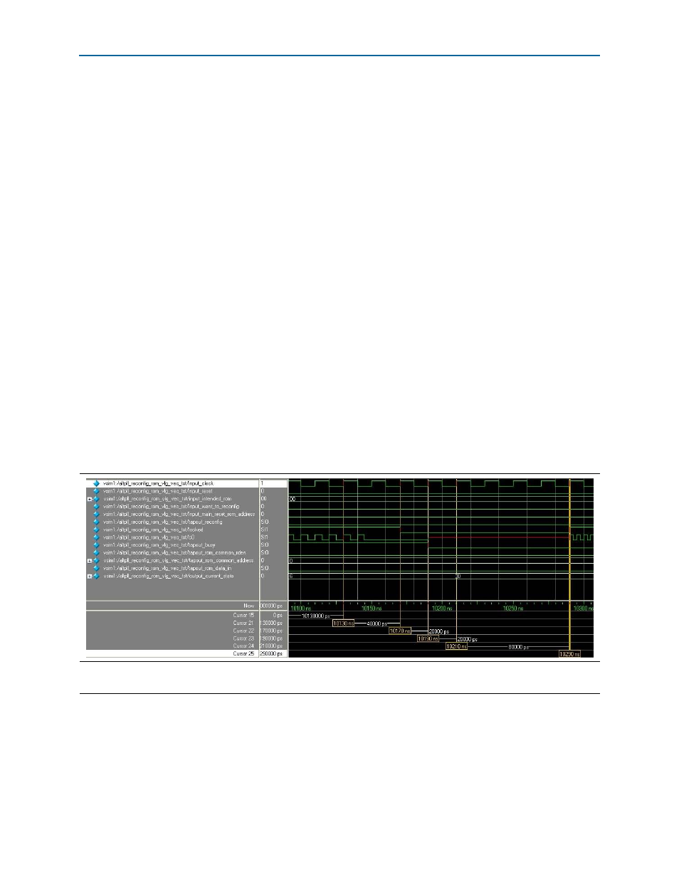
shows the final part of the reconfiguration process.
At 10,130 ns, the
tapout_busy
signal remains asserted. The
output_current_state
signal remains at a value of
6
. Therefore, the state machine is still waiting for the
tapout_busy
signal to be deasserted. The
c0
signal is still at 100 MHz and the
locked
signal remains asserted, which means the PLL is still locked to a 100-MHz signal.
Figure 27. PLL Reconfiguration (10,000 to 10,400 ns)
Note to
(1) From
c0
= 100 MHz to
c0
= 200 MHz.