Altera Cyclone III LS FPGA Development Board User Manual
Page 20
2–12
Chapter 2: Board Components
Configuration, Status, and Setup Elements
Cyclone III LS FPGA Development Board Reference Manual
© October 2009 Altera
Corporation
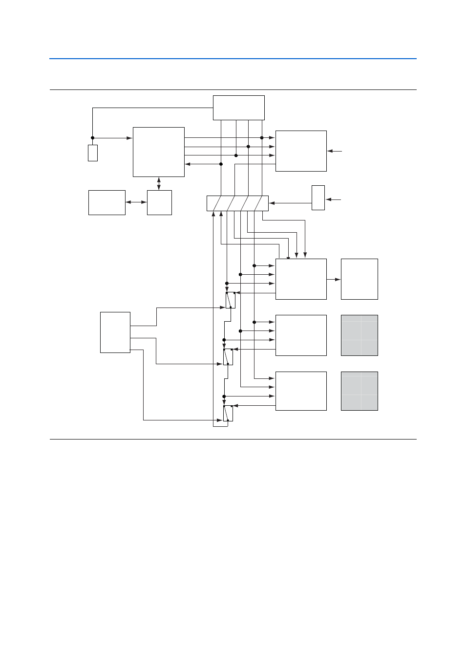
For normal JTAG operation, the shunt jumper must be removed from the
JTAG_AT_SEL
jumper (J12). To connect a device or interface to the chain, the
corresponding shunt must be installed onto the JTAG chain header (J11). Remove all
of the shunt jumpers to only have the FPGA in the chain.
The MAX
II CPLD EPM2210 System Controller must be in the chain to use the power
monitor or the Board Test System. For this setting, install the upper-most jumper
shunt onto the JTAG chain header (J11).
When a shunt is installed on the JTAG_AT_SEL jumper (J12), the default JTAG chain
breaks and the MAX II EPM2210 System Controller gains control of the FPGA JTAG.
For more information on the anti-tamper example design, refer to
<install_dir>\kits\cycloneIIILS_3cls200_fpga\examples\max2\at_example\
readme_at_example.txt
.
Figure 2–4. JTAG Chain
Embedded
Blaster
GPIO
TCK
EP3CLS200
FPGA
EPM2210
System
Controller
HSMC
Port A
HSMC
Port B
GPIO
TMS
GPIO
TDO
GPIO
TDI
JTAG Master
GPIO
DISABLE
JTAG Master/Slave
JTAG Master/Slave
Installed
HSMC
Card
Installed
HSMC
Card
TCK
TMS
TDI
TDO
TCK
TMS
TDI
TDO
TCK
TMS
TDI
TDO
TCK
TMS
TDI
TDO
JTAG Slave
JTAG Slave
Analog
Switch
Analog
Switch
EPM2210_JTAG_EN
HSMA_JTAG_EN
ALWAYS
ENABLED
(in chain)
SW2.5
10-pin
JTAG Connector
Flash
Memory
Analog
Switch
HSMB_JTAG_EN
Embedded
Blaster
Connection
USB
PHY
J4
J8
2x3 Jumper
J11
NC
NC
NC
NC
SEL
JTAG_AT_SEL
J12
Break JTAG chain for
MAX II EPM2210
System Controller
GPIO to control
FPGA JTAG
Analog
Switch