Fast passive parallel download, Fast passive parallel download –10 – Altera Transceiver Signal Integrity Development Kit, Stratix IV GX Edition User Manual
Page 20
2–10
Chapter 2: Board Components
Configuration, Status, and Setup Elements
Transceiver Signal Integrity Development Kit,
November 2011
Altera Corporation
Stratix IV GX Edition Reference Manual
A green USB-Blaster LED (D7) indicates the USB-Blaster activity. The embedded
USB-Blaster is automatically disabled when an external USB-Blaster is connected to
the JTAG chain at header J28.
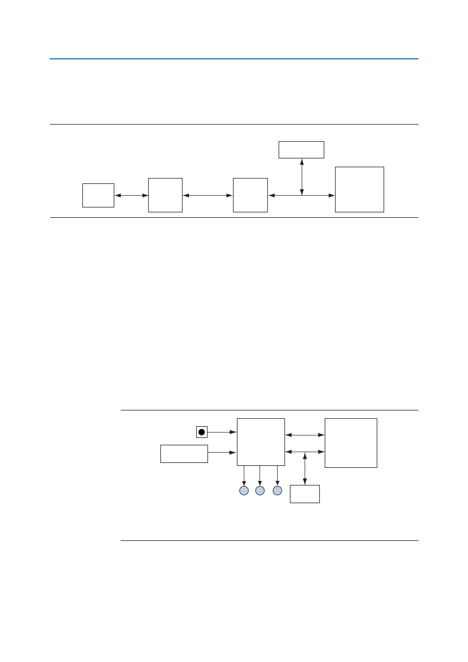
Fast Passive Parallel Download
shows the block diagram for the MAX II+Flash FPP configuration. This
method is used for automatic configuration of the FPGA with the configuration
programming image stored in the flash memory. The FPP download controller is
implemented within an Altera MAX II EPM1270F256C3N CPLD (U32). This
controller, together with the Numonyx PC28F512P30BF 512-Mb CFI NOR-type flash
device (U39), performs FPP configuration upon board power-up or reset. The CPLD
shares the flash interface with the FPGA. The configuration program select jumper,
PGMSEL (J62) selects between two Programmer Object Files (.pof)—factory .pof or
user .pof files stored in the flash. The FPP controller uses the Altera Parallel Flash
Loader (PFL) megafunction to configure the FPGA by reading data from the flash and
converting it to FPP format. This data is written to the FPGA’s dedicated
configuration pins during configuration. The configuration mode select signals,
MSEL[2:0]
, are pulled to [0,0,0] on the board for FPP mode configuration. Three
green configuration status LEDs (D16–D18) indicate the status of the FPP
configuration.
Figure 2–3. Embedded USB-Blaster
USB
USB Type-B
Connector
USB 2.0
PHY
USB FIFO Bus
MAX II
CPLD
JTAG
JT
A
G
JTAG
Header
Stratix V GX
FPGA
Figure 2–4. MAX II+Flash FPP Configuration
RESET button
(SW8)
PGMSEL
Jumper (J62)
MAX II CPLD
(U32)
FPP
Configuration
Flash
Flash
Flash
(U39)
FA
CT
OR
Y LED
(D17)
USER LED
(D18)
ERR
OR LED
(D16)
Stratix IV GX
FPGA
(U33)