Power measurement, Power measurement –22 – Altera Transceiver Signal Integrity Development Kit, Stratix IV GX Edition User Manual
Page 32
2–22
Chapter 2: Board Components
Components and Interfaces
Transceiver Signal Integrity Development Kit,
November 2011
Altera Corporation
Stratix IV GX Edition Reference Manual
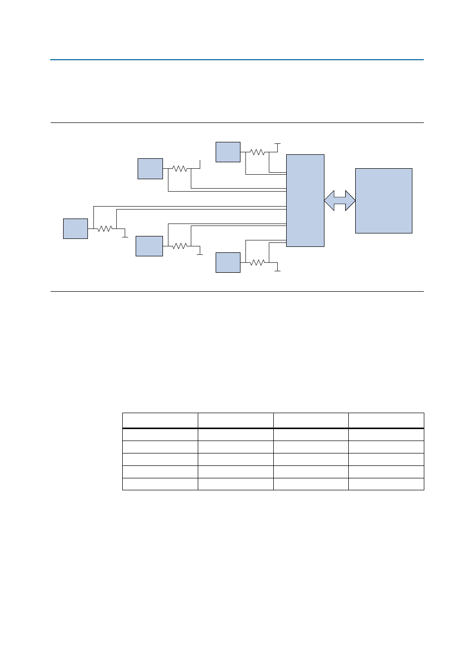
Power Measurement
shows the block diagram for the power measurement circuitry.
Power measurement is provided for five FPGA power rails (0.9-V V
CC
core plus the
transceiver power rails—V
CCRT
, V
CCL
, V
CCH
, and V
CCA
). The power measurement is
implemented by a multi-channel differential 24-bit Linear Technology LT2418 (U14)
delta-sigma analog-to-digital converter (ADC) and sense resistors to measure the
small voltage drop across the resistors. This ADC connects to the FPGA via a serial
peripheral interface (SPI) bus. The FPGA handles all power measurement processing
and display to the LCD. A rotary switch (SW16) controls the selection of specific
power rail to be displayed on the LCD.
lists the power rails being
measured along with the value of the sense resistor used for each rail.
Figure 2–8. Power Measurement Circuit
Stratix IV GX
FPGA
(U33)
SPI Bus
LTC2418
(U14)
0p9V
R3
Reg
(U1)
R20
Reg
(U6, U9)
R25
Reg
(U11)
Reg
(U10, U12)
R24
R11
Reg
(U4)
V
CCRT
V
CCL
V
CCH
V
CCA
Table 2–22. Power Rail Measurements
Power Rail
Name Voltage (V)
Ref Des
Rsense (
Ω)
V
CC
0.9
R3
0.001
V
CCRT
1.1
R20
0.009
V
CCL
1.1
R25
0.009
V
CCH
1.4 / 1.5
R24
0.009
V
CCA
2.5 / 3.0
R11
0.009
Note to
(1) The power rail measurements whose values on the engineering silicon board differ from the production silicon
board are listed in
.