Components and interfaces, Temperature measurement, Components and interfaces –20 – Altera Transceiver Signal Integrity Development Kit, Stratix IV GX Edition User Manual
Page 30: Temperature measurement –20
2–20
Chapter 2: Board Components
Components and Interfaces
Transceiver Signal Integrity Development Kit,
November 2011
Altera Corporation
Stratix IV GX Edition Reference Manual
lists the flash memory map storage for two FPGA bitstreams (factory and
user) as well as 40 MB of reserved user space for PFL configuration settings storage,
software binaries, and other data relevant to the targeted FPGA design (that is, Nios
applications). For the EP4SGX230KF40 FPGA device, each FPGA bitstream can be a
maximum of 94.54 Mb (less than 12 MB). Hence, the factory and user POF space is set
at 12 MB.
lists the flash memory device component reference and manufacturing
information.
Components and Interfaces
This section describes the temperature measurement and power measurement
circuitries and the board’s communication ports.
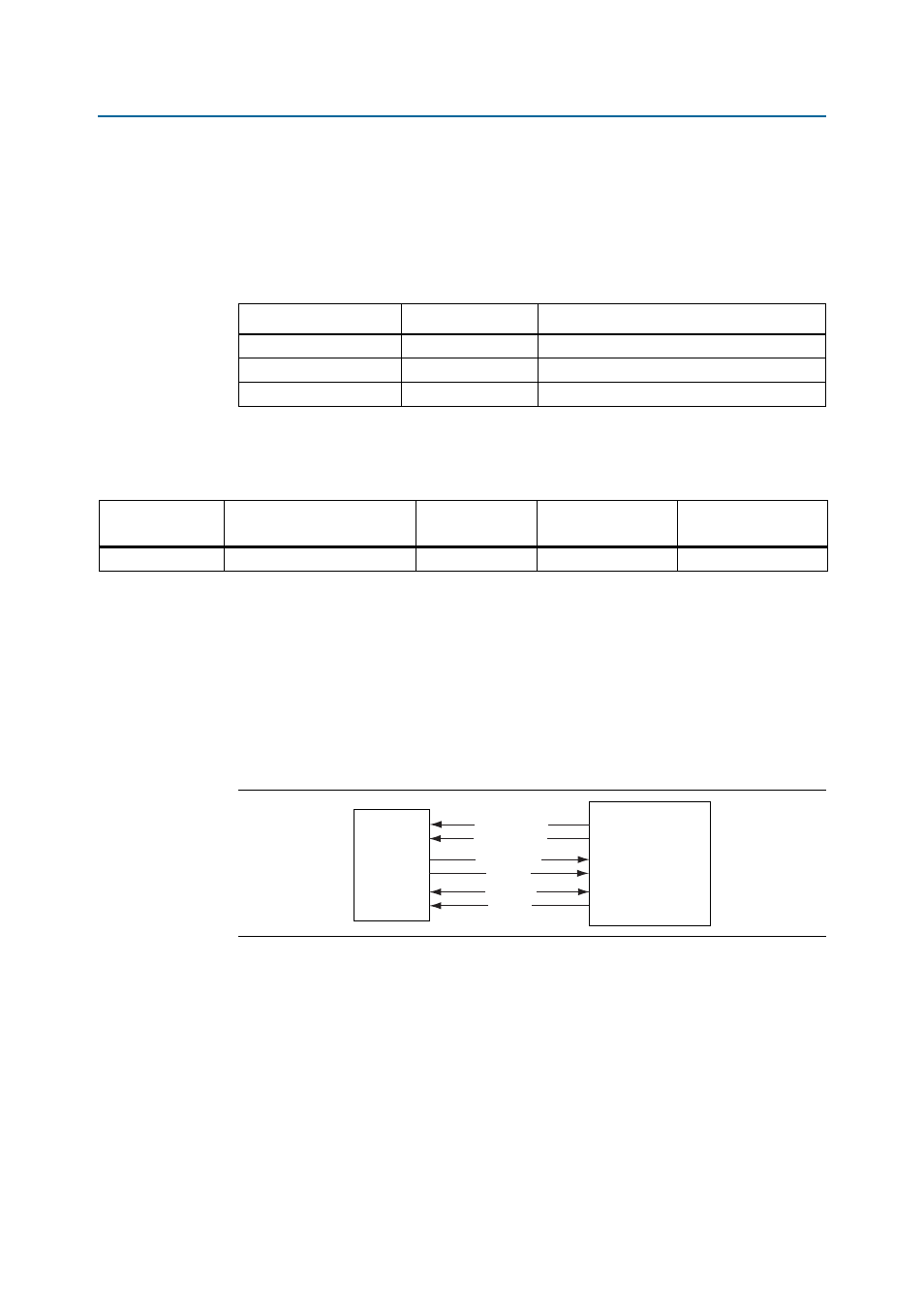
Temperature Measurement
shows the block diagram for the temperature measurement circuitry.
Table 2–17. Flash Memory Map
Name
Size (Mbyte)
Address
Reserved
40
0x0180.0000 – 0x03FF.FFFF
USER
12
0x00C0.0000 – 0x017F.FFFF
FACTORY
12
0x0000.0000 – 0x00BF.FFFF
Table 2–18. Flash Memory Device Component Reference
Board Reference
Description
Manufacturer
Manufacturing
Part Number
Manufacturer
Website
U39
512-Mb NOR-type flash
Numonyx
PC28F512P30BF
Figure 2–7. Temperature Measurement
Stratix IV GX
FPGA
(U33)
MAX1619
(U15)
TEMPDIODE_N
TEMPDIODE_P
ALERTn
OVERTEMPn
SMBCLK
SMBDATA