Jtag programming header, Status and setup elements, Status leds – Altera Transceiver Signal Integrity Development Kit, Stratix IV GX Edition User Manual
Page 21: Jtag programming header –11, Status and setup elements –11, Status leds –11
Chapter 2: Board Components
2–11
Configuration, Status, and Setup Elements
November 2011
Altera Corporation
Transceiver Signal Integrity Development Kit,
Stratix IV GX Edition Reference Manual
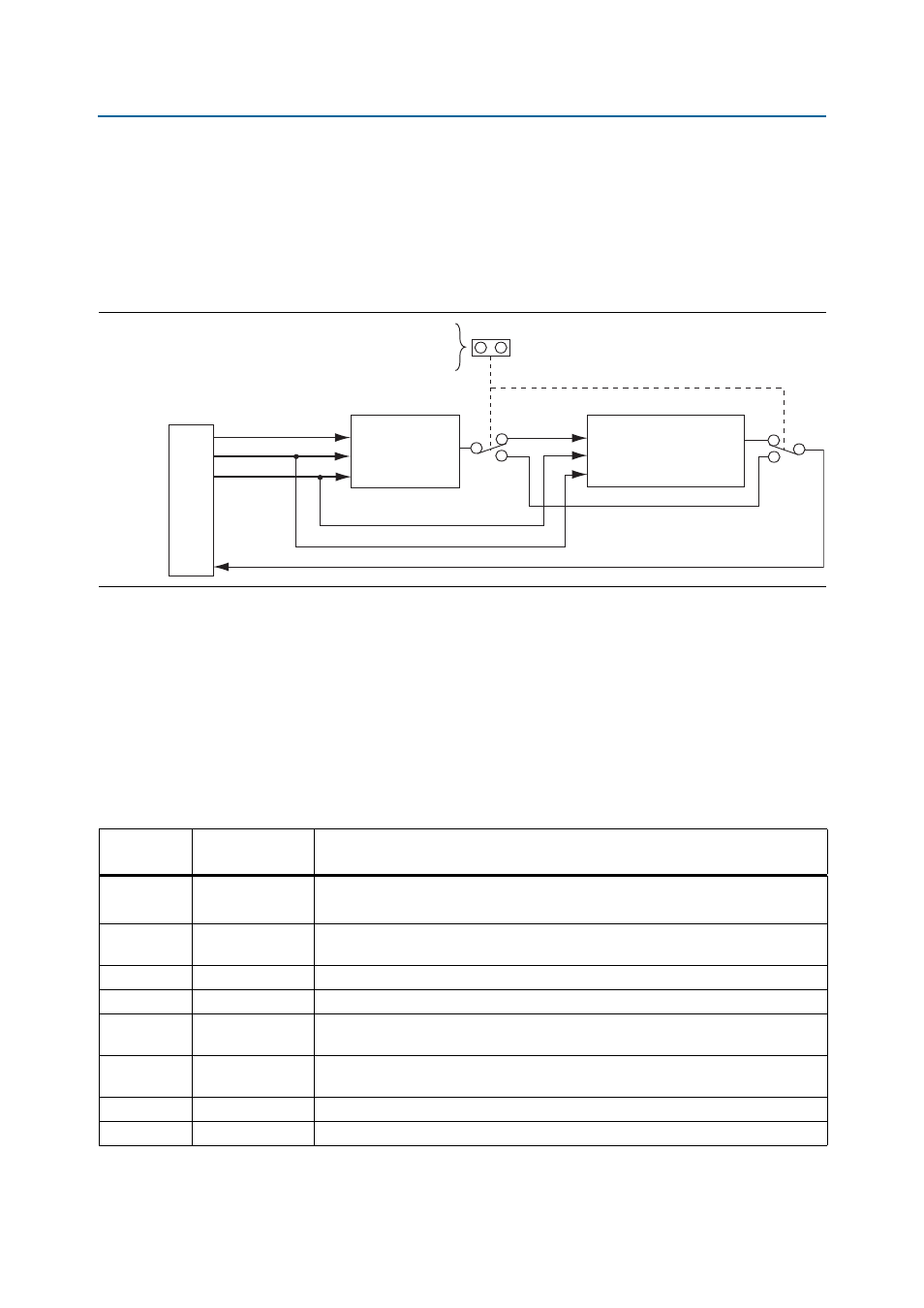
JTAG Programming Header
shows the schematic connections for the dedicated JTAG programming
header (J28). This header provides another method for configuring the FPGA (U33)
using an Altera USB-Blaster with the Quartus II Programmer running on a PC. The
MAX II JTAG configuration jumper (J26) allows the MAX II CPLD device to be
removed from the JTAG chain so that the FPGA is the only device on the JTAG chain.
Status and Setup Elements
The development board includes board-specific status LEDs, jumpers, and switches
for enabling and configuring various features on the board, as well as a
16 character × 2 line LCD for displaying board power and temperature
measurements. This section describes the status and setup elements.
Status LEDs
lists the LED board references, names, and functional descriptions.
Figure 2–5. JTAG Programming Header
J28
U33
Stratix IV GX
Stratix IV GX
and MAX II
External
USB-Blaster
Header
Remove jumper to
remove MAX_FPP device
from JTAG header
J26
TDI
TMS
TCK
LAST_TDO
S4GX_TDI
S4GX_TDO
JTAG_TMS
JTAG_TCK
JTAG_TMS
JTAG_TCK
MAX_FPP_TDI MAX_FPP_TDO
U32
MAX II CPLD
9
5
1
3
Table 2–5. Board-Specific LEDs (Part 1 of 2)
Board
Reference
LED Name
Description
D3
POWER
Blue LED. Illuminates when board power switch (SW1) is on.
(Requires 14–20 V input to DC input jack J1)
D6
FAN
Amber LED. Illuminates to indicate an FPGA over-temperature condition. A fan sink
must be attached to the FPGA and running to prevent overheating.
D7
BLASTER
Green LED. Blinks to indicate the embedded USB-Blaster activity.
D16
ERROR
Red LED. Illuminates when a configuration error has occurred.
D17
FACTORY
Green LED. Illuminates when the factory POF image is successfully programmed into
the FPGA.
D18
USER
Green LED. Illuminates when the user POF image is successfully programmed into the
FPGA.
D19
TX
Green LED. Blinks to indicate Ethernet transmit activity.
D20
RX
Green LED. Blinks to indicate Ethernet receive activity.