How to use / operation – Brennenstuhl Solar Energy Set SES P4033 Solar celltype Mono-crystalline 2x20Wp Panel dimensions 592x 641x25mm Inverter 150W User Manual
Page 7
Solar Energy Set SES P4033 V3
GB
7
How to use / Operation
Solar charge regulator
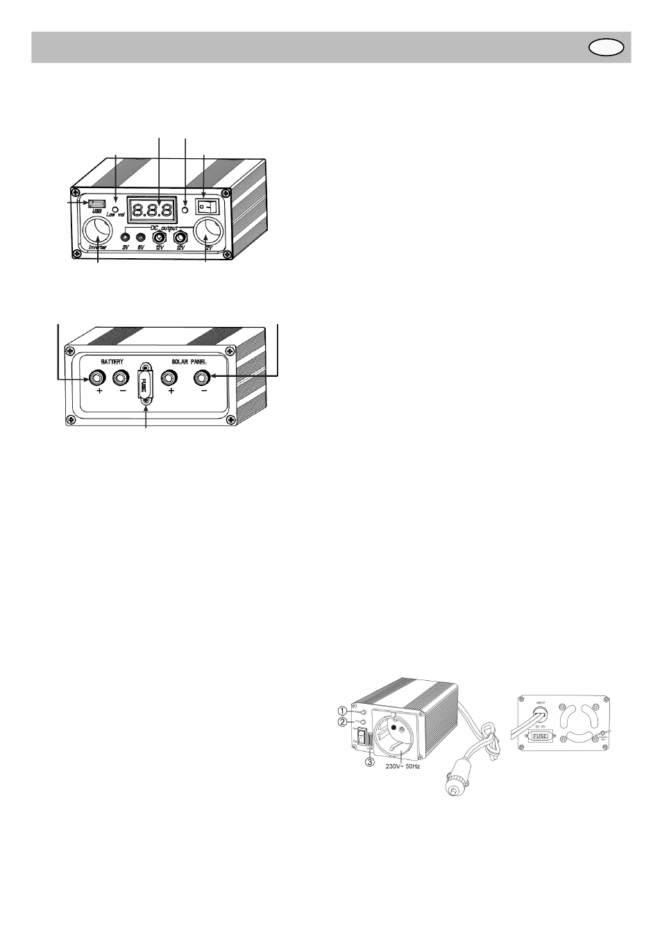
FRONT
Digital voltage meter
Over discharge indicator
USB
output
Switch for digital voltage meter
12V female CLA output
Inverter female CLA output
ON/OFF Switch
REAR
Connection to battery
Connection to Solar Panel
Fuse
●
Do not operate the charge controller without a suitable battery
(12 V ≥ 33 Ah) to avoid damaging the connected devices.
●
Please make sure that the connection to this charge regulator
is tight and secure.
●
The charge regulator needs to be turned on in order to activate
all its functions.
●
A digital voltage meter is included to show real time battery
voltage. A push button switch is available to turn on the digital
display only when needed, in order to save valuable electricity.
●
The charge regulator provides following protections to maintain
system’s proper working condition:
A. Over-discharge protection: When the electricity level of
the battery goes too low (lower than 11±0.3 V), the solar
charge regulator will automatically shut off power output to
prevent the battery from over discharge. “Low vol”- indicator
on the front side of charge regulator will be on. The output to
appliance will resume when battery voltage increases back
to 12 V. Please disconnect the appliance, and charge the
battery until full.
B. Over-charge protection: When the electricity level of the
battery goes too high (higher than 14.0-14.5 V), the system
controller will automatically shut off power input to prevent
damage to the battery. The input from Solar module will
resume when battery voltage decreases to 13.5 V.
C. Over-load protection: When output power goes too big, the
fuse in the system controller will be melted to prevent dam-
age to the controller itself. Fuse has to be replaced in order
to bring the controller back to working condition in this case
(car fuse 10 A – red).
Connecting sockets:
Front side
DC output:
1 x 12 V cigarette lighter adapter socket: Can be used to
power appliances that have a cigarette lighter adapter,
2 x 12 V DC connector sockets (6,3 mm)
1 x 6 V DC connector socket (3,5 mm)
1 x 3 V DC connector socket (3,5 mm)
Inverter
1x cigarette lighter adapter socket to connect the power
inverter:
This output draws power directly from rechargeable battery
and is not regulated by this solar charge regulator.
USB
1x USB output socket (5 V DC): Can be used to charge elec-
tronic devices that get power from USB port (MP3 player,
mobile phone, ...).
Digital Voltmeter
●
Display
●
ON/OFF switch
Back side
●
Fuse
●
Connection terminal “BATTERY”
●
Connection terminal “SOLAR”
Power inverter
●
Use with suitable loads only (230 V AC, max. 150 W, modi-
fi ed sine wave).
●
Connect power inverters only to the inverter socket
(do not exceed max. power rating)! Do not connect
other devices, as they may exhaust and thus damage
the rechargeable battery.
●
Connect the power inverter to the solar charge controller
(power inverter jack).
Make sure you do not plug the power inverter into the
12 V jack. If you do, the built-in charge controller may
fuse.
●
Switch the power inverter on fi rst as the source, then
switch on the load.
Caution: When connecting a device with a motor or com-
pressor to the power inverter make sure the peak output
of the power inverter is about three times as high as the
nominal power of the electrical device because the mak-
ing current is much higher than the nominal value of the
device.
●
The power inverter will emit an acoustic signal if the battery
voltage is too low. Switch the connected device off, discon-
nect the power inverter and charge the battery.
●
The power inverter will emit an acoustic signal if the total
power of the device to be operated exceeds the output
power of the inverter.
●
The same thing happens if the temperature of the power
inverter exceeds 65 °C due to extended use.
FRONT BACK
Status Indicators
Green „POWER“ indicator (1) on: power inverter is on and ready for
use. Green „POWER“ indicator off: power inverter is off
Red „FAULT“ indicator (2) on: malfunction
USB Charging Socket (3)
Can be used to charge electrical devices supplied with power from
a USB port, such as MP3 players, mobile phones, etc. (5 V DC,
500 mA max).