CIRCUTOR computer SMART Series (Available until stock) User Manual
Page 22
M98235701-03-12A
Computer Smart 6/Computer Smart 12
- 21 -
Table 5-1: Plug&Play Errors and messages displayed on the screen
ERROR
Description
Some stages can be cancelled by the leakage current alarm or forced in the
On/Off/Auto Setup. The Plug&Play function cannot be executed in these cases.
Phase not found. Cosine out of range (between 0.62 and 0.99, inductive).
Unstable measurement. Changes in load during the process.
Error in the measurement of the largest capacitor.
No capacitors found.
Incorrect measurement of the number of capacitors.
Incorrect measurement of the ratio of the first capacitor.
Possible error in the program calculated.
C/K out of range.
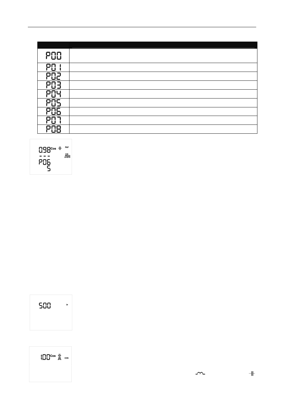
Example of a Plug&Play error screen:
In this case, the Plug&Play function will calculate the Phase (not displayed on the
screen) and 5 stages or steps, the P06 error will occur when calculating the Program,
so that it will be displayed in its place, since the C/K parameter can not be calculated,
displaying the following ---.
The first line will always show the current cosine to check the need to change to a
different screen when the parameters that have been calculated are correct.
In the case of the P00 error, i.e., when capacitors have been deactivated by a leakage current alarm or
forced in the On/Off/Auto Configuration, the P&P function will not be started until the problem is resolved. The
Plug&Play function will assist during the installation of the power factor compensation system or when there
are changes in the system (new regulator, new cabling, new stage, etc.). To do so, the potential problems in
faulty capacitors must be resolved before the P&P function is activated, by means of carrying out the
corresponding maintenance activities or replacing them, while configuring all stages in the default Auto mode.
IMPORTANT: Conditions for the correct operation of the Plug&Play option:
-
The system must be maintained with a cosine of 0.62 to 0.99 (inductive) during the process.
-
The system's power must be stable. Any important changes in load (>10% in less than 20 seconds)
would lead to the incorrect calculation of the capacitor power ratings.
-
There must be enough current in the system at the regulator's input, i.e., >100 mA AC.
-
When there is a load offset, the correct operation of the Plug&Play function will depend on the phase
where the current transformer was connected to.
IMPORTANT: After the P&P process is complete, the CT primary must be configured (IP screen) before the
unit can measure the power and current correctly.
Setup Screen of the Current Transformer's Primary, Ip (PC2, TypeC2):
The current of the Current Transformer's (CT) primary is configured with this
parameter, depending on the type of CT installed to measure the installation's current.
The adjustment range is 5 to 9999. The CT's secondary is configured to 5 A AC by
default.
ϕϕϕϕ
Objective Cosine Setup Screen (PC3, TypeC2):
This parameter is used to fix the desired power factor for the installation. The regulator
will add the number of capacitors needed to adjust the value as close as possible to the
objective value. The regulation process is carried out in stages, so that this will not
affect any switching operations until the non-compensated demand is at least 70% of
the power of the smallest stage or the excess compensation is 70% of the power of the
smallest stage. Any value ranging from 0.7 Inductive (
) to 0.7 Capacitive (
) can
be configured.