CIRCUTOR computer SMART Series (Available until stock) User Manual
Page 12
M98235701-03-12A
Computer Smart 6/Computer Smart 12
- 11 -
3
GENERAL FEATURES
The Computer Smart 6/Smart 12 power factor regulators
measure the grid cos
φ
and regulate the connection and
disconnection of capacitors to correct it. The Computer
Smart 6 and Smart 12, models can control a different
number of relay outputs each.
Type
Maximum no. outputs
Computer Smart 6
6 relay outputs, plus an alarm relay
Computer Smart 12
12 relay outputs, plus an alarm relay
Here are some of the most important features of this series of regulators:
- Power and voltage measurement circuits in the same inputs.
- Different models for different voltages (110, 230, 400 and 480 Vac).
- Indiscriminate use of the 50 or 60 Hz frequency.
- Easy to install, with no need to use tools.
- Dimensions in compliance with DIN 43 700 (144 x 144 mm front panel).
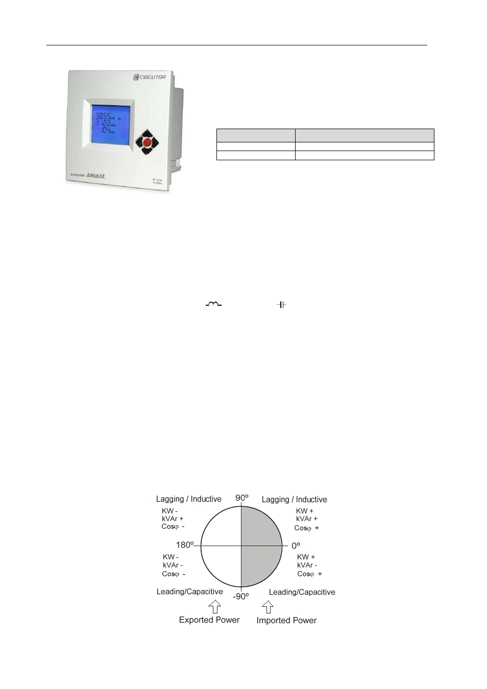
- 4-quadrant control (see Fig.3.1), with indication about the stages connected, indication of the cos
φ
,
type of reactive power (inductive
or capacitive
), and display of energy import or export
(EXPORT icon).
- LCD screen with 15 digits and seven segments, on 4 lines, plus 55 icons to display the different
operating conditions.
- Grid analyzer function, with the measurement of many different system parameters.
- Measurement of the leakage current with an associated alarm, disconnection of capacitors and
search and deactivation of the faulty capacitor.
- Simple configuration, with only 5 keys, with a Plug&Play function and no need to disconnect the
power supply.
- Many different programs, from 1:1:1:1 to 1:9:9:9. This can divide the total power in up to 46 steps in
Smart 6 and up to 100 steps in Smart 12.
- FCP system that minimises the number of capacitor connections and disconnections.
- RS-485 Communications (Modbus protocol), to supervise and display the different regulator
parameters. The SCADA Power Studio software can be used to display and configure the said
parameters.
- 4-Quadrant measurement and compensation:
Fig. 3.1.- Signs in 4-quadrant measurements