CIRCUTOR computer SMART Series (Available until stock) User Manual
Page 23
M98235701-03-12A
Computer Smart 6/Computer Smart 12
- 22 -
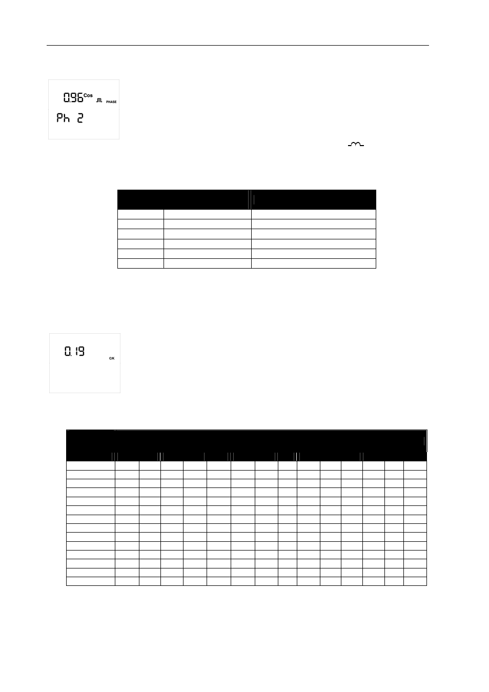
Setup Screen of the Voltage and Current Phase (PC4, TypeC2):
This parameter can be used to adapt the regulator to the different connection options of
the power supply and measurement cables and those of the current transformer to the
phases of the three-phase system. The default setup is shown in Fig.2.2, i.e., the
current transformer on phase L1 and the voltage is measured in the L1, L2 and L3
phases. It is often hard to check whether the unit has been cabled like this or not, so
that one of the Ph 1 to Ph 6 options shown in Table 5.2 must be chosen to cater for this
situation. Each option should be selected during the installation adjustment, when
inductive reactive power is being consumed with a cos
ϕ
of 0.6 to 1, inductive (
). The options can be
viewed until the screen shows a cos
ϕ
of 0.6 to 1 (the cosine displayed on this screen is for information
purposes only and can not be edited).
Table 5-2.- Computer Smart Phase Selection Options
Screen
V Measurement
phases
CT Connection Phase
Ph 1
L1-L2-L3
L1
Ph 2
L1-L2-L3
L2
Ph 3
L1-L2-L3
L3
Ph 4
L1-L2-L3
L1 (Inverted Transformer)
Ph 5
L1-L2-L3
L2 (Inverted Transformer)
Ph 6
L1-L2-L3
L3 (Inverted Transformer)
C/K Factor Setup Screen (PC5, TypeC2):
This parameter is adjusted with the reactive current supplied by the smallest capacitor
step, measured on the current transformer's (CT) secondary. Its adjustment value will
depend on the power of the smallest capacitor step, the CT ratio and the grid voltage.
The value can be adjusted between 0.02 and 1.00.
Table 5.3 shows the values that must be used to adjust the C/K for a grid with 400 Vac
between phases, the different transformer ratios and the powers of the smallest stage.
In the case of other voltages or conditions that have not been included in the table, the
C/K value can be obtained with a simple calculation, as shown next.
Table 5-3.- C/K Factor, in accordance with the smallest stage power and current transformer (CT) ratio
CT Ratio
(I
p
/I
s
)
Power in kvar of the smallest stage, in kvar, at 400 V
2.5
5.00
7.5
10.0
12.5
15.0
20.0
25.0
30.0
40.0
50.0
60.0
75.0
80.0
150/5
0.12
0.24
0.36
0.48
0.60
0.72
0.96
200/5
0.09
0.18
0.27
0.36
0.45
0.54
0.72
0.90
250/5
0.07
0.14
0.22
0.29
0.36
0.43
0.58
0.72
0.87
300/5
0.06
0.12
0.18
0.24
0.30
0.36
0.48
0.60
0.72
0.96
400/5
0.05
0.09
0.14
0.18
0.23
0.24
0.36
0.48
0.58
0.72
0.87
500/5
0.07
0.11
0.14
0.18
0.22
0.29
0.36
0.45
0.54
0.72
0.87
600/5
0.06
0.09
0.12
0.15
0.18
0.24
0.30
0.36
0.48
0.60
0.72
0.90
0.96
800/5
0.07
0.09
0.11
0.14
0.18
0.23
0.27
0.36
0.45
0.54
0.68
0.72
1000/5
0.05
0.07
0.09
0.11
0.14
0.18
0.22
0.29
0.36
0.43
0.54
0.57
1500/5
0.05
0.06
0.07
0.10
0.12
0.14
0.19
0.24
0.29
0.36
0.38
2000/5
0.05
0.07
0.09
0.11
0.14
0.18
0.22
0.27
0.28
2500/5
0.06
0.07
0.09
0.12
0.14
0.17
0.22
0.23
3000/5
0.05
0.06
0.07
0.10
0.12
0.14
0.18
0.19
4000/5
0.05
0.07
0.09
0.11
0.14
0.14