CIRCUTOR computer SMART Series (Available until stock) User Manual
Page 31
M98235701-03-12A
Computer Smart 6/Computer Smart 12
- 30 -
5.5
ERROR Messages: errors and alarms
In the Normal mode, the screen will show a code with the type of error or alarm detected when the unit
detects an error or alarm. The errors and alarms that can be detected and the messages displayed on the
screen are summarised in the following table:
Table 5-5: Errors and messages displayed on the screen
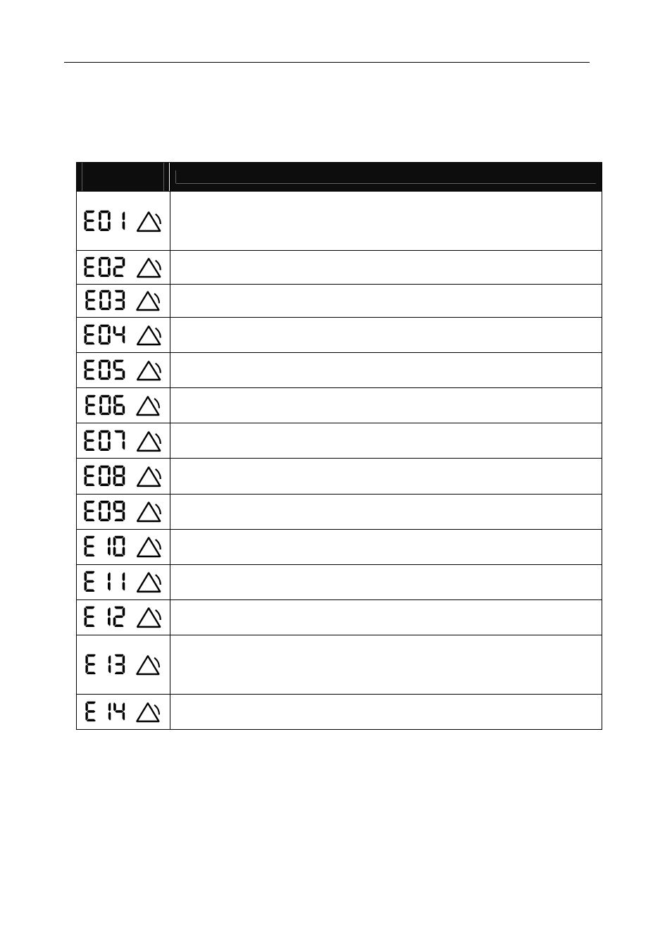
ERROR
message
Description
No current. Due to a load current that is lower than the minimum or because the
current transformer (CT) is not connected. Appears when the current on the
transformer's secondary is lower than 50 mA. The unit disconnects the
capacitors automatically.
Over-compensation. The unit measures capacitive power but all stages are
disconnected. This can be due to the incorrect adjustment of the C/K parameter.
Under-compensation. The unit measures inductive power but all stages are
disconnected. This can be due to the incorrect adjustment of the C/K parameter.
Over-current. The current measured exceeds the nominal current by + 20 %.
The nominal current is considered to be that of the TC primary.
Overvoltage. The voltage measured exceeds the nominal voltage by +15 %.
Low voltage. The voltage on some of the phases is 10% less than the nominal
voltage.
THD U alarm. The THDU levels are higher than those configured in the THDU
Alarm (PA3).
THD I alarm. The THDI levels are higher than those configured in the THDI
Alarm (PA3).
Leakage Alarm. The leakage current is higher than that configured in the
Leakage Current Alarm (PA4).
Cosine Alarm
ϕ
. The cosine
ϕ
is out of the range configured in the Cosine Alarm
ϕ
(PA2).
Temperature Alarm. The temperature measured is higher than that configured in
the Temperature Alarm (PA5).
Repeated Leakage Alarm. Repeated leakages have been detected by the
system, although these have not been caused by a capacitor.
Leakage Alarm in Capacitors. Leakage has been detected that is caused by one
of the capacitors and this capacitor is disabled. The capacitors that have been
disabled will start to flash on the screen. In addition, message E13 will be
displayed. To enable them again, see the Leakage Alarm configuration (PA4).
The Leakage Alarm has been configured, but the equipment does not detect the
connection of the leakage current transformer.
When an alarm or error is detected, the equipment will display it when said alarm has been enabled (see the
Setup section 5.6). The backlight (display light) will flash when the alarm has been triggered and an error
code will be displayed on the measurement screens, in addition to the alarm icon.
The unit is configured by default with the 6 first alarms enabled (E01 to E06).
5.6
Alarm Relay
The unit has a switched relay that is exclusively used as the alarm output. The possible errors or alarms can
be separately associated to the activation of the alarm relay on the Alarm Enable screen (PA1). To see the
connections, check Section 2.2.