CIRCUTOR computer SMART Series (Available until stock) User Manual
Page 26
M98235701-03-12A
Computer Smart 6/Computer Smart 12
- 25 -
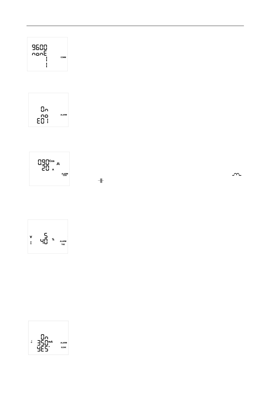
Communications Setup Screen (PC9, TypeC2):
This screen is used to configure various communications-related parameters (RS-485)
for the unit:
The baud rate (9600, 19200 or 38400)
The parity (nonE - None, EvEn - Even, odd - Odd)
The number of stop bits (1 or 2)
The peripheral number assigned (1-255)
Alarm Enable Screen (PA1, TypeC3):
This screen will be used to configure each type of error or alarm (from E01 to E14, see
Table 5-5). Enable or disable and associate the said error or alarm to the activation of
the alarm relay.
The following can be configured for each error or alarm:
On/Off: Enable or disable the error or alarm.
Yes/No: Associate to the alarm relay or not.
Alarm Displayed
Cosine Alarm Setup Screen
ϕϕϕϕ
(PA2, TypeC2):
These parameters establish the action limits of the alarm. After the alarm is enabled
(from PA1), the system will display an error code (see Table 5-5) when the cosine
value
ϕ
is lower than the value configured and the current is higher than the value
configured.
The cosine value configured can range from 0 to 0.99, in inductive (
) and
capacitive (
). The current value configured is rated in A and it can range from 0 to
9999 A.
This alarm is activated with a 15 second delay.
THD Alarm Setup Screen (PA3, TypeC2):
These parameters establish the action limits of the alarm. After the alarm is enabled
(from PA1), the system will display the corresponding error code (see Table 5-5) when
the THD Voltage or THD Current value is higher than the value configured.
The values configured are expressed in % and can range from 0 to 99%.
This alarm is activated with a 15 second delay.
Setup Screen of the Leakage Current (PA4, TypeC2):
There are various alarms related to leakage currents (E09, E12, E13 and E14, see Section 5.7).
The second parameter is used to establish the action limits of alarm E09. When the alarm is enabled (from
PA1), the system will display the corresponding error code E09 (see Table 5-5) when the leakage current
measurement is higher than the value configured.
The value is configured in mA and it can range from 10 to 1000 mA. The alarm delay cannot be configured
and it is lower than 2 seconds, depending on the leakage current measurement when compared to the limit
established.
The first configurable parameter (On/Off) is used to connect and disconnect all
capacitors after the E09 alarm has been tripped, in order to search for the capacitor/s
responsible for the leakage. Once the capacitor has been detected, it is disconnected
so that it can not be connected again. In this case, the unit will display the
corresponding error code (see Table 5.5) with the capacitors that have been
disconnected. These capacitors will flash every second on any of the measurement
screens.