Correct incorrect – CIRCUTOR computer SMART Series (Available until stock) User Manual
Page 9
M98235701-03-12A
Computer Smart 6/Computer Smart 12
- 8 -
2.2
Equipment Installation
2.2.1
Mechanical Installation
In mechanical terms, the equipment is installed in a cabinet's front panel or in a panel. The panel fixing drill
must be drilled in compliance with DIN 43 700, (dimensions: 138+1x138+1 mm).
2.2.2
Connections
The following points must be checked before the unit is powered:
The installation and maintenance of the equipment must be performed by qualified and
authorised staff, in accordance with the national and international Standards.
All connections must remain inside the electrical panel.
Take into account that, when the device is connected, the terminals may be hazardous to the
touch, and opening the covers or removing elements may expose these parts. Do not use the
device until it is fully installed.
This regulator has a series of associated capacitor units that remain charged up to 5 minutes
after the unit has been disconnected from the grid. Make sure that all capacitors have been
discharged before handling the unit.
The installation of an external current transformer (CT) is necessary to measure the current. Usually, the
transformation ratio of this CT is In/5 A, where In must be a minimum of 1.5 times over the total maximum
current of the load.
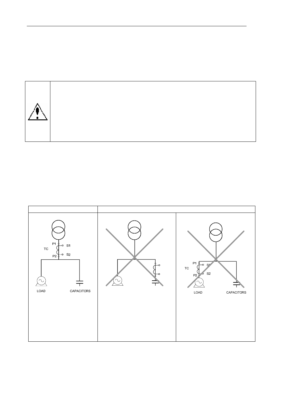
The current transformer (CT) must be installed on the connection point where all of the loads' current
circulates and where the current of the capacitors will be compensated (see Fig. 2.1).
The current transformer (CT) should preferably be connected to phase L1, while the voltage connections
should be connected to phases L1, L2 and L3 (see diagram in Fig. 2.2). Connections P1, P2, S1 and S2
shown on the said diagrams should be respected. In case the connection layout mentioned above is not
respected, the phase must be adjusted, following the procedure described in section 5.5.
CORRECT
INCORRECT
The current transformer (CT)
must measure the joint current
of the capacitors and the loads.
If this does not work, make
sure that the CT is not short-
circuited.
TC
S1
S2
P1
P2
LOAD
CAPACITORS
When the CT is connected in this
position, NO CAPACITORS WILL
BE CONNECTED, even when
inductive loads are present. The
unit
will
not
perform
the
compensation functions.
When the CT is connected in this
position, ALL CAPACITORS WILL
BE CONNECTED. However, they
will not be disconnected when the
load decreases.
Risk of over-compensation in the
grid with no load.
Fig. 2.1.- Location of the current transformer