6 single-pump system installation, Single-pump system installation, Fig. 13 – Crompton Controls DCM User Manual
Page 28: Go to chapter 6 and, 6single-pump system installation
Advertising
Emotron AB 01-2120-01r2
Single-Pump System Installation
27
6
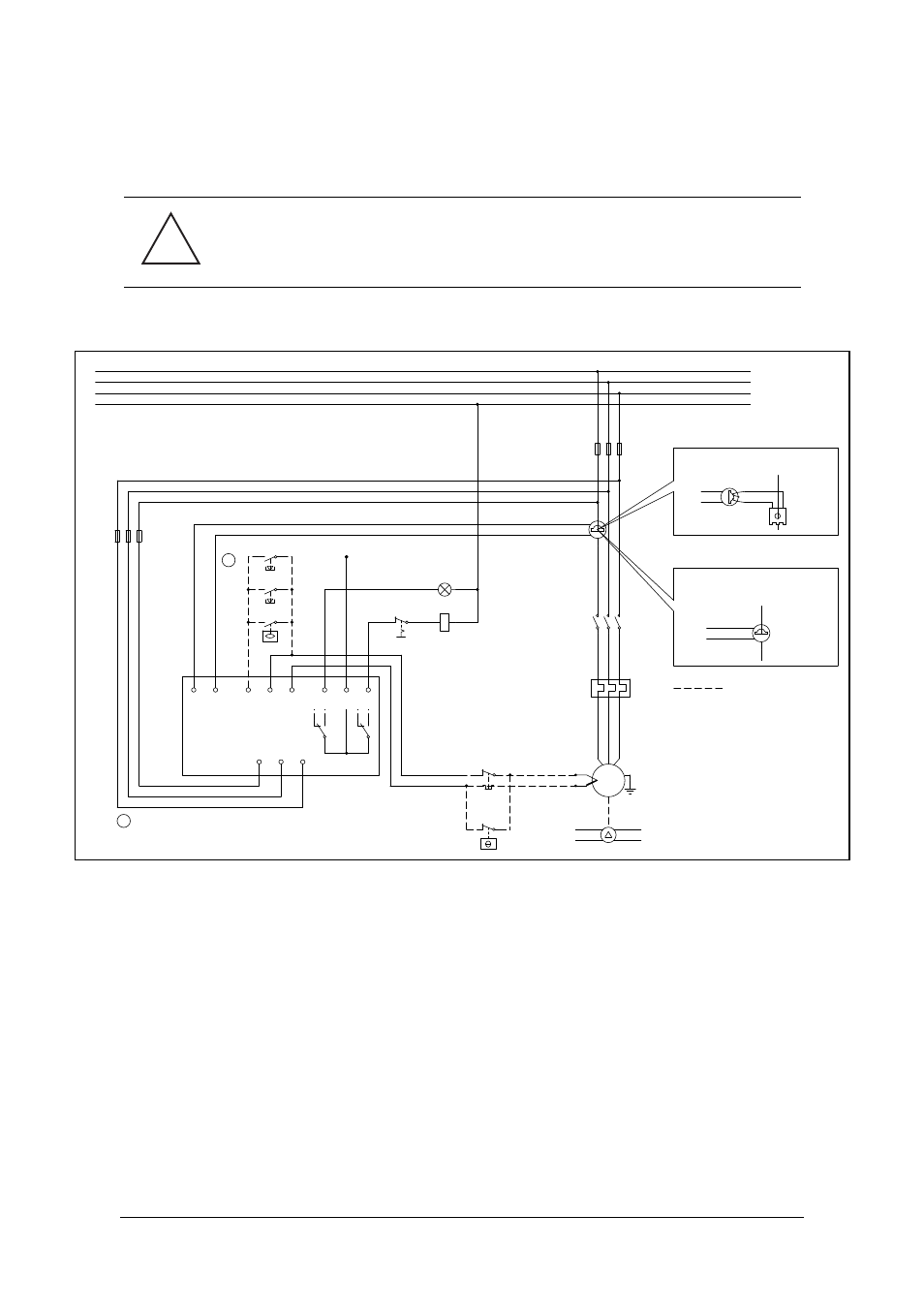
Single-Pump System Installation
Fig. 13 Single-pump system installation example (alternatively see Chapter 13).
CAUTION: Before carrying out any work, check that any automatic
control equipment, etc., is disconnected from the power supply
and cannot become live.
!
L1
L2
L3
N
Thermo-
contact
S1
S2
Dig
SGND Temp
Pump
C
Allarm
L3
L2
L1
CTM xxx
L1
Number of primary and secondary windings see Table 2
Number of primary windings see Table 1
Alternativ anslutning
Exceeding 100 Amps
Upto 100 Amp
S
S
L1
Standard
transformer
CTM 010
DCM
A
A
Selection, see Manual:
Digital Input connection
Dig and SGND, term. 3 and 4.
K1
F1
U
V
W
M
Autoset
Reset
High level
K1
Alarm
1
2
3
4
5
6
7
8
9
11
13
Max 240VAC
Thermistor PTC
-
+
F1
Stop
Max. 10 A
Advertising