Outstation cables – Interspace Industries TheatreCue 16 Way V4 System - 16 Outstations User Manual
Page 31
Designed and created by:-
Built By
Cable types
A:
Belden 9463
B:
Electra
C: CAT5 (
20AWG
24AWG
One pair wired to XLR pins 2 & 3.
Remaining 3 pairs wired to XLR Pin 1)
EAS7201P
31.
What’s the cable Limit?
There is no magic cable length at which the Cue Light
system suddenly stops operating.
We have included a few examples of test setups to the right
to give an idea of what the system’s limits actually are.
We have suggested
(6500 ft)
architecture of your choice by u
that the Cue Light system be restricted
to a maximum of about 40 Outstations and a total of 2,000m
of cable. These numbers are fairly conservative
and provide a reasonable safety margin.
You should not experience any trouble wiring up the network
with the
sing cable lengths
and Outstation numbers as per the table on page 28.
Outstation Cables
(Continued)
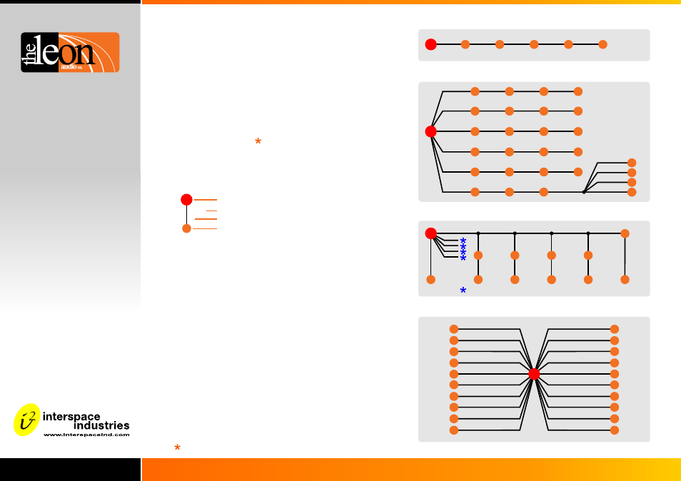
Network architecture: star, daisy chain, loop or combination of these.
M
6
6
6
6
6
200m
200m
200m
200m
200m
A
A
A
A
A
Fig 1. Cable total: 1,000m Outstations: 36
Fig 2. Cable total: 3,800m Outstations: 50
A: 100m
A: 100m
A: 100m
A: 100m
A: 600m
Fig 3. Cable total: 3,700m Outstations: 60
100m
100m
100m
100m
B
B
B
B
Fig 4. Cable total: 4,000m Outstations: 43
500m
500m
200m
100m
300m
C
C
B
B
B
A: 200m
A: 200m
A: 200m
A: 200m
A: 200m
3
3
3
3
3
6
6
6
6
6
6
6
6
2
4
6
500m
B
M
4 x B: 50m (no Outstations connected)
4
0
4
B: 200m
B: 200m
B: 300m
C: 500m
C: 500m
B: 100m
B: 200m
B: 200m
2
2
2
2
2
2
2
2
2
B: 150m
B: 150m
B: 150m
B: 150m
M
0
B: 100m
B: 50m
B: 50m
M
6
200m
A
Master Station
Cable segment length (metres)
Cable type
Number of Outstations at this mode.
2
0
100m
100m
100m
A
A
B
100m
100m
100m
A
A
B
100m
100m
A
A
100m
100m
A
A
100m
100m
A
A
100m
B
100m
B
100m
B
100m
B
100m
B
100m
B
100m
B
100m
B
300m
500m
B
C
500m
C
2
2
2
2
2
2
2
2
2
2
2
2
2
2
2
2
2
2
2
2
2
2
2
300m
B
M
1
B: 50m
1
1
1
B: 50m
B: 50m
B: 50m
The limit in Figure 1 was voltage drop on the cable. A thicker
cable would be needed to allow for a longer cable run.
In Figures 2-4, connection to the Master Station was via a
patch panel with parallel wired connectors.
The limit for Figures 2-4 is the power supply’s ability to
provide the inrush current that the Outstations draw when
power is first applied.
The “worst case” situation occurs when the cable lengths
are very short. In this case the inrush current is at its highest
and the power supply can only drive 40 Outstations.
As the cable lengths are increased, the inrush currents are
reduced due to the cables’s resistance, allowing more than
40 Outstations to be connected.