Diagnostics, Outstation test, Button & lamp test – Interspace Industries TheatreCue 16 Way V4 System - 16 Outstations User Manual
Page 46
Designed and created by:-
Built By
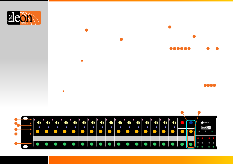
This test is used to check the operation of buttons and
lamps on the Master Station.
The
on channels 1-16 will chase sequentially in rows.
The sequence is followed by and
on together but dimmed. The sequence then repeats.
to the right of channel 16 also flash sequentially.
Pressing any button will halt the chase sequence and light
adjacent to the button that was pressed.
Pressing the Go or Standby buttons on channels 1-16 will
light the button pressed.
Press 3 buttons until all lamps on the Master Station’s
front panel light (takes about 4 seconds), then release the
buttons.
To exit this test, press the 3 buttons again or cycle the
mains power.
lamps
Lamps
lamp(s)
Pressing the Group button on
channels 1-16 will light the Fault, Group A & B and Call
lamps for the channel pressed.
Pressing the 6 buttons to the right of channel 16:-
Pressing the red Beep button will light lamps on
channels 1 to 8.
Pressing the blue Dimmer button will light the same lamps
on channels 9 to 16.
Pressing Group A Standby or Go button lights the button of
same name on channels 1-8.
Pressing Group B Standby or Go button lights the button of
same name on channels 9-16.
Diagnostics
46.
Outstation test
1
2
3
4
5
6
7
8
9
10
11
12
13
14
15
16
Short
Power
A
B
A
B
A
B
A
B
A
B
A
B
A
B
A
B
A
B
A
B
A
B
A
B
A
B
A
B
A
B
Button & Lamp test
This test is used to check operation of Outstation lamps,
communication to and from the Master Station and cable
voltage drop.
Press 2 buttons until all lamps on the Master Station’s
front panel light (takes about 4 seconds), then release the
buttons.
To exit this test, press either of the 2 buttons or cycle the
mains power.
The Go and Standby lamps on all outstations flash
alternately. Outstation Standby colour changes between red
& yellow on every 2nd flash of the Standby lamp.
As all Outstations are active, this provides the maximum
voltage drop on the interconnecting cables. When the
number of Outstations placed on the end of a cable run
exceeds the number specified in the table on page 28, the
excessive voltage drop will cause the Outstations to
automatically dim their lamps to reduce power consumption
and hence reduce the voltage drop. The automatic dimming
of the Outstation lamps is an indicator that the limits of the
cable run are being approached.
The maximum voltage drop will be higher if Outstations are
configured to allow both Go and Standby lamps to be on at
the same time.
1 2
4
3
5 6
5
6
8
8
7
7
1 2
4
3
1
2
3
4
5
6
7
8
9
10
11
12
13
14
15
16
Power
Theatre Cue Light
Master QLM16i2 Mk4
www.interspaceind.com
Innovation by:-
Built By:-
Group
Call
Fault
Standby
GO
Fault
Group
Call
Standby
GO
Fault
Group
Call
Standby
GO
Fault
Group
Call
GO
Standby
Fault
Group
Call
Standby
GO
Fault
Group
Call
Standby
GO
Fault
Group
Call
Standby
GO
Fault
Group
Call
Standby
GO
Fault
Group
Call
Standby
GO
Fault
Group
Call
Standby
GO
Fault
Group
Call
Standby
GO
Fault
Group
Call
Standby
GO
Fault
Group
Call
Standby
GO
Fault
Group
Call
Standby
GO
Fault
Group
Call
Standby
GO
Fault
Group
Call
Standby
GO
+ Sb/y = short
+ Go = long
Beep
+ Sb/y = up
+ Go = down
Dimmer
Reset Faults
Group A
Standby
Standby
GO
Sensors
1
2
3
4
1
2
3
6
Group B
GO
8
7
Fault
Unsafe
Safe
4
5