2 installation in a smartcontroller system – Adept T2 Pendant User Manual
Page 14
Installation
14
Adept T2 Pendant User’s Guide, Rev D
2.2
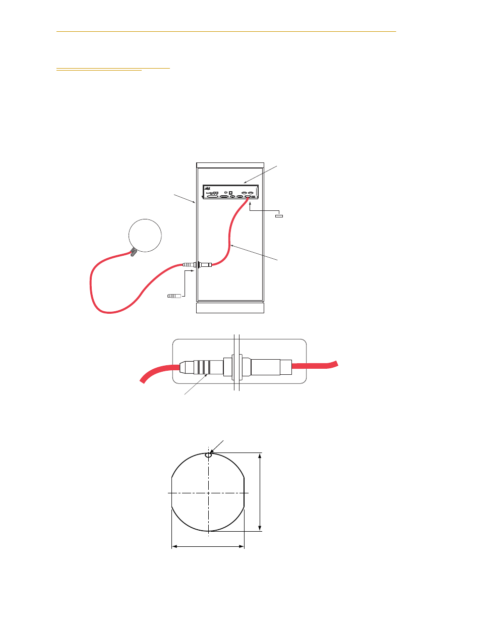
Installation in a SmartController System
1. Plug the pendant cable connector into the matching adapter cable connector.
NOTE: The T2 pendant uses push-pull connectors. Line up the red dots to
insert the connectors, pull back on the outer sleeve to remove.
2. If you are using an equipment cabinet, the adapter cable connector can be
bulkhead-mounted to the inside wall. See
Figure 2-2 Panel Cut-out Dimensions
3. Plug the adapter cable into the XMCP connector on the SmartController.
Figure 2-1. Installing Pendant in Equipment Cabinet
Figure 2-2. Panel Cut-out Dimensions
From T2 Pendant
Push-Pull connector: to remove,
pull back on outer sleeve.
To controller
Wall or door of
equipment cabinet
HPE
1.1 1.2
XMCP
XUSR
S
C
r
ell
or
t
n
o
Ct
r
a
m
S
XFP
OK
HD
XSYS
1 2 3
SW1
LAN
ES
24V 5A
XDIO
R
XDC1 XDC2
SF
-+ -+
SmartServo
Device Net
Eth 10/100
RS-232
RS-422/485
Equipment Cabinet
(user-supplied)
T2 Pendant
Bypass Plug
(supplied
with pendant)
D-Sub
Bypass Plug
(supplied with controller)
SmartController
T2 Adapter Cable
(supplied with T2 Pendant)
SW 22.6
Red Dot
∅ 24.1