Joint mode – Adept T2 Pendant User Manual
Page 29
Pendant Control Modes
Adept T2 Pendant User’s Guide, Rev D
29
Joint Mode
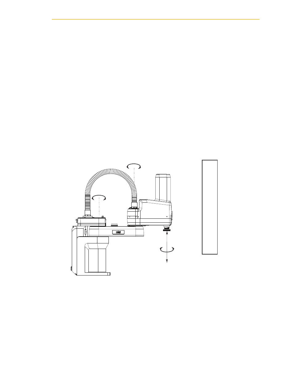
When Joint mode is selected, movement is about the axis of the specified joint. The
following figure shows an Adept SCARA robot with three rotational joints (joints 1, 2, and
4) and one translational joint (joint 3). Positive rotation of joints 1 and 2 is
counterclockwise as viewed from above. Positive rotation of joint 4 is clockwise as viewed
from above. Positive movement of joint 3 is downward.
Select a joint for motion using the Joint/Axis control buttons - see the following figure.
Pressing the ‘+’ button moves the robot joint in the positive direction. Pressing the ‘–’
button moves the robot joint in the negative direction.
Different robots or motion devices will have the different joint numbers assigned to their
joints. When you first move an unfamiliar robot using Joint mode, set the monitor speed
to 10 or lower, put the robot in a safe area, and carefully move the robot using the
different joint numbers to verify how the pendant moves the robot. See the
documentation for the motion devices you are using for details on their joint assignments.
Figure 4-5. Joint Mode (Four-Axis SCARA)
J1
J2
J3
J4
J5
J6
Joint 1
Joint 2
Joint 4
Joint 3
Joint 1
Joint 2
Joint 3
Joint 4
T2 Pendant Joint/Axis
Control Buttons