1 summary chart – AMETEK SLH Series RevC User Manual
Page 36
Operation
Sorensen SLH-Series DC High Power Electronic Load
17
-/+
DC INPUT Binding Posts
The negative (left) and positive (right) terminal of load input connector
•
+
:
Connect to the positive and ground output for a positive output power supply
•
-
:
Connect to the negative and ground output for a negative output power supply.
NOTE:
Before testing, ensure that the voltage and current do not to exceed the maximum
rating (see Table 1-2) of each SLH-series DC load and the connection method
utilized (see Section 2.2).
Also check the polarity (Section 3.10.5) of DC input connection before testing.
18 V
SENSE
Used to measure the specific voltage points through the V-sense BNC - CLIP cable.
19 I
MONITOR
Provides the load current waveform output to an oscilloscope to evaluate the current
waveform of a power supply under test.
See Table 1-2 for voltage/current relationship of I-monitor outputs in SLH-series DC series
modules.
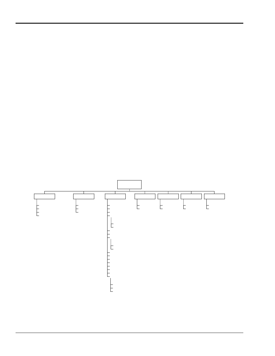
3.1.1 Summary
Chart
The front panel controls are summarized in Figure 3-2.
CC: Constant Current
CR: Constant Resistance
CV: Constant Voltage
CP: Constant Power
MODE (3)
PRESET
DWM/DAM Display
DVM/DAM
PRESet (7)
G/NG Volt Limits
G/NG Curr. Limits
G/NG Power Limits
AUTO
ON
Vsense
Load On Voltage
Load Off Voltage
AUTO
Rang II
Range
iStart
iStop
iStep
PStart
PStop
Pstep
Vthreshold
Normal
OCP
OPP
Test
LIMIT (12)
HI
LO
LEVEL (9)
ON
OFF
LOAD (8)
DYNamic
STAtic
DYN/STA (10)
ON
OFF
SHORT (11)
SLH DC Loads
Button Functions
Figure 3-2 Organization of Front Panel Controls of SLH-Series DC Plug-in Module
3-6
M540074-01
Rev C