Screening, Fc510x: d-sub, 9 pin, Cable colours – BECKHOFF FC5101 User Manual
Page 17
Eiserstraße 5 / D-33415 Verl / Telefon 05246/963-0 / Telefax 05246/963-149
17
·
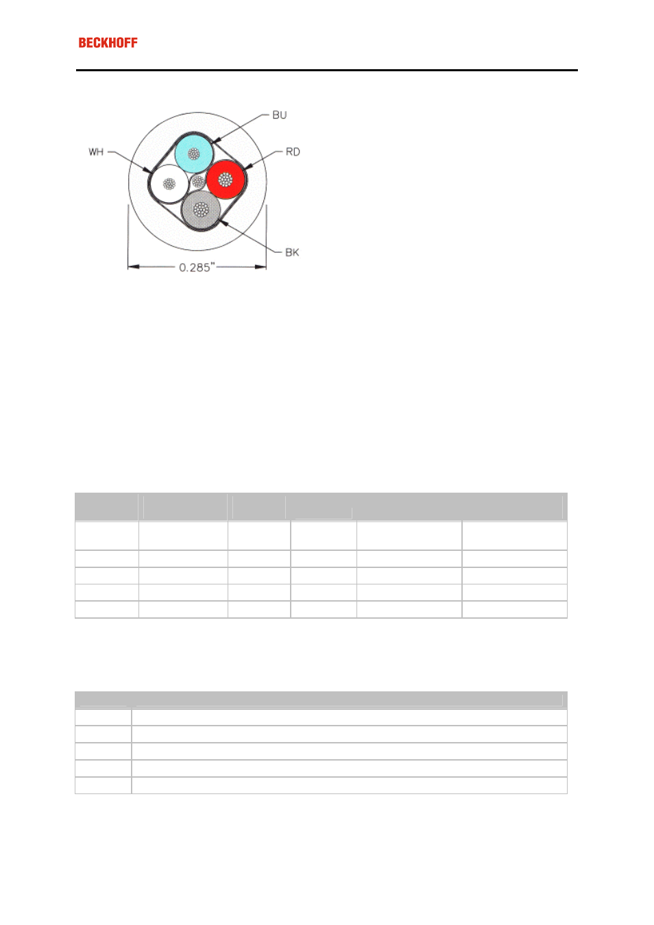
corresponds to the DeviceNet "Thin Cable" specification
Screening
The screen is to be connected over the entire length of the bus cable, and only galvanically grounded at one
point, in order to avoid ground loops.
The design of the screening, in which HF interference is diverted through R/C elements to the mounting rail
assumes that the rail is appropriately earthed and free from interference. If this is not the case, it is possible that
HF interference will be transmitted from the mounting rail to the screen of the bus cable. In that case the screen
should not be attached to the couplers - it should nevertheless still be fully connected through.
Notes related to checking the CAN wiring can be found in the Trouble Shooting section.
Cable colours
Suggested method of using the Beckhoff CAN cable on Bus Terminal and Fieldbus Box:
BK51x0
pin
Fieldbus Box
pin
FC510x
pin
Function
ZB5100 cable co-
lour
ZB5200 cable co-
lour
1 3
3 CAN
Ground
black/ (red)
black
2 5
2 CAN
Low
black
blue
3
1
5
Screen
Filler strand
Filler strand
4 4
7 CAN
high
white
white
5 2
9 not
used
(red)
(red)
FC510x: D-sub, 9 pin
The CAN bus cable is connected to the FC5101 and FC5102 CANopen PCI cards via 9-pin sub-D sockets, with
pins assigned as follows.
Pin
Assignment
2
CAN low (CAN-)
3
CAN ground (internally connected to pin 6)
5
Screen
6
CAN ground (internally connected to pin 3)
7
CAN high (CAN+)
The unlisted pins are not connected.
Note: An auxiliary voltage of up to 30 V DC may be connected to pin 9. Some CAN devices use this to supply
the transceiver.