Pdo mapping – BECKHOFF FC5101 User Manual
Page 47
Eiserstraße 5 / D-33415 Verl / Telefon 05246/963-0 / Telefax 05246/963-149
47
In the case of receive PDOs, the timer is used to set a watchdog interval for the PDO: the application is in-
formed if no corresponding PDO has been received within the set period.
The FC510x can in this way monitor each individual PDO.
Notes on PDO Parameterisation
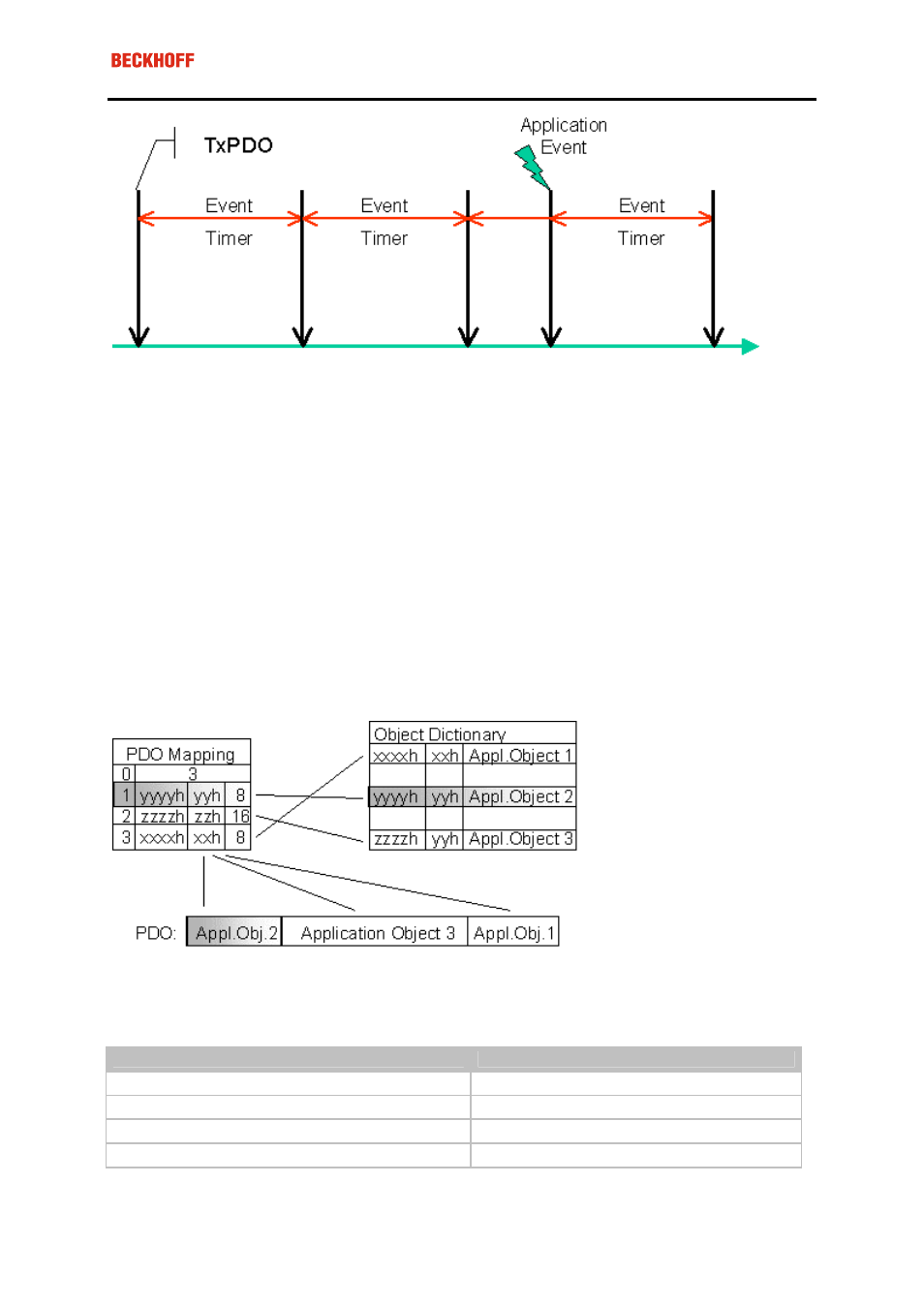
PDO Mapping
PDO mapping refers to mapping of the application objects (real time data) from the object directory to the proc-
ess data objects. The CANopen device profile provide a default mapping for every device type, and this is ap-
propriate for most applications. Thus the default mapping for digital I/O simply represents the inputs and out-
puts in their physical sequence in the transmit and receive process data objects.
The default PDOs for drives contain 2 bytes each of a control and status word and a set or actual value for the
relevant axis.
The current mapping can be read by means of corresponding entries in the object directory. These are known
as the mapping tables. The first location in the mapping table (sub-index 0) contains the number of mapped
objects that are listed after it. The tables are located in the object directory at index 0x1600ff for the RxPDOs
and at 0x1A00ff for the TxPDOs.
Digital and analog input/output modules: Read out the I/O number
The current number of digital and analog inputs and outputs can be determined or verified by reading out the
corresponding application objects in the object directory:
Parameter
Address Object directory
Number of digital input bytes
Index 0x6000, Subindex 0
Number of digital output bytes
Index 0x6200, Subindex 0
Number of analog inputs
Index 0x6401, Subindex 0
Number of analog outputs
Index 0x6411, Subindex 0