2interfacesintroduction, 1compinsintroduction, 2cr-netconnection – CREATOR CR-PGMIII User Manual
Page 11: 3cr-linkconnection, 4usbinterface, 4pgmⅢ programmable ethernet control system, 2 interfaces introduction, 1 com pins introduction, 2 cr-net connection, 3 cr-link connection
CREATOR CHINA 2011-03
WWW.CREATOR1997.COM
4
PGMⅢ Programmable Ethernet Control System
16)DIGITAL I/O——Extension I/O Module Slot
Can extend the I/O control module number by
inserting the extension module here.
17) UART—— Extension COM Module Slot
Can extend the COM interface number by
inserting the extension COM module here.
18) Grounding Pole
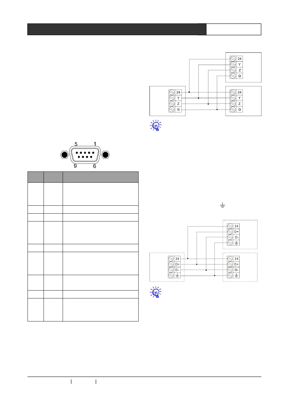
2.2 Interfaces Introduction
2.2.1 COM Pins introduction
Pin
Signal
Introduction
1
RXD
RS-485 protocol, connected along
with the pin 9 to be used as the
RS-485”-”
2
RXD
RS-232 protocol, receive data
3
TXD
RS-232 protocol, send data
4
TXD+
RS-485 protocol, connected along
with the pin 6 to be used as the
RS-485”+”
5
GND
Signal Grounding
6
RXD+
RS-485 protocol, connected along
with the pin 4 to be used as the
RS-485”+”
7
RTS
RS-232
protocol,
request
for
sending
8
CTS
RS-232 protocol, cancle sending
9
TXD
RS-485 protocol, connected along
with the pin 1 to be used as the
RS-485”-”
2.2.2 CR-NET Connection
The connection of the CR-NET equipment
supports both series and parallel connection
types. And attention should be paid to the
corresponding of the 24,Y,Z,G. Please refer
to the following diagram:
During the installation and using, plugging
and unplugging equipment while power is ON
should be avoided to reduce the risk of
malfunction of the controller due to the electric
shock caused.
2.2.3 CR-LINK Connection
The connection of the CR-NET equipment
supports both series and parallel connection
types. And attention should be paid to the
corresponding of the 24,D+,D-, . Please refer to
the following diagram:
During the installation and using, plugging
and unplugging equipment while power is ON
should be avoided to reduce the risk of
malfunction of the controller due to the electric
shock caused.
2.2.4 USB Interface
The USB interface is used to communicate
with the PC during programming and diagnosis.
The connection diagram is as following: