Chaptertwo,detailedcontrollerspecifications, 1front&therearpanel, Chapter two,detailed controller specifications – CREATOR CR-PGMIII User Manual
Page 9: 2pgmⅢ programmable ethernet control system, 1 front & the rear panel
CREATOR CHINA 2011-03
WWW.CREATOR1997.COM
2
PGMⅢ Programmable Ethernet Control System
Chapter Two,Detailed Controller
Specifications
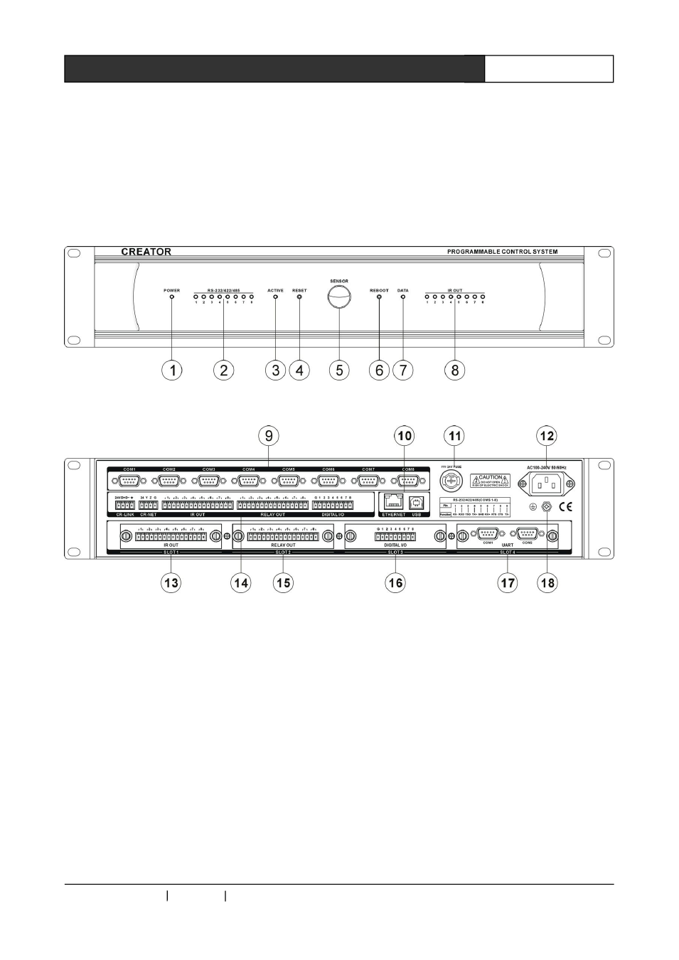
2.1 Front & the rear Panel
CR-PGMⅢ Front Panel:
CR-PGMⅢ Rear Panel:
1) POWER——Power Indicator
2) RS-232/422/485——COM data
communication indicator
Indicates the data communication status of
the 8 COM interfaces: when there is data sending
or receiving, the corresponding indicator will be
on. The “TX” is for data sending indication, and
the “RX” is for data receiving indication.
3) ACTIVE——Status Indicator
4) RESET—— Reset Button
When the controller is into an abnormal status
due to being downloaded with wrong program (a
infinite loop for example), the RESET button can
be pressed to erase the wrong program.
Operation
Instruction:
First
power
off
the
controller; then power on the controller while
press and hold the RESET button. The “beep”
sound will start and continue. Release the RESET
button after about 7 ~8 beeps, and the wrong
program will be erased from the controller.
5) SENSOR—— IR Receiving Window
CR-PGMⅢ
Programmable
Ethernet
Controller provided built-in IR Learning Module,
and SENSOR can receiving the IR Signal to be