DFI PT631-IPM User Manual
Page 25
Advertising
25
2
Hardware Installation
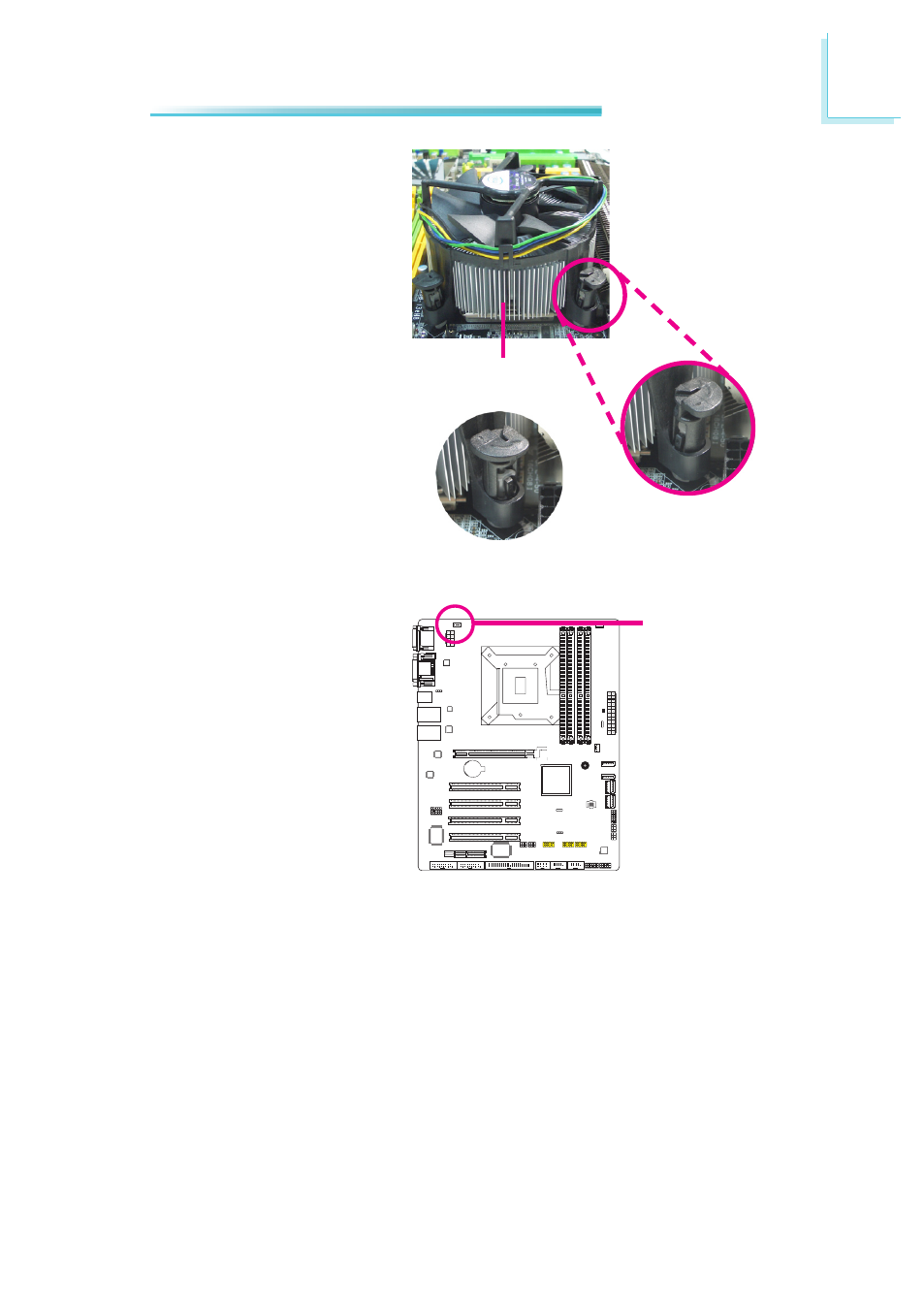
4. Rotate each push-pin ac-
cording to the direction of
the arrow shown on top of
the pin.
Push down two pushpins
that are diagonally across
the heat sink. Perform the
same procedure for the
other two push-pins.
Heat sink
“Locked” position of
push-pin
5. Connect the CPU fan’s ca-
ble to the CPU fan connec-
tor on the system board.
“Unlocked” position
of push-pin
CPU fan
connector
Advertising