2 mechanical installation onto valve or gearbox, 3 type “bl” drive: splined drive application – Flowserve MX Electronic Actuator User Manual
Page 21
21
Limitorque MX Electronic Actuator FCD LMENIM2306-06 – 10/13
flowserve.com
Pilot installation
Slide pilot into thrust base assembly and secure with the two washers and screws. Tighten fully.
3.1.3 Type “BL” Drive: Splined Drive Application
Steel alloy splined nuts are provided to a standard involute spline category for rising and rotating stem valves per
customer requirements. Disassembly and reassembly is the same as the B4 base and the torque nut. See Section 3.1.1,
Type “B” Bases: Torque-only Applications.
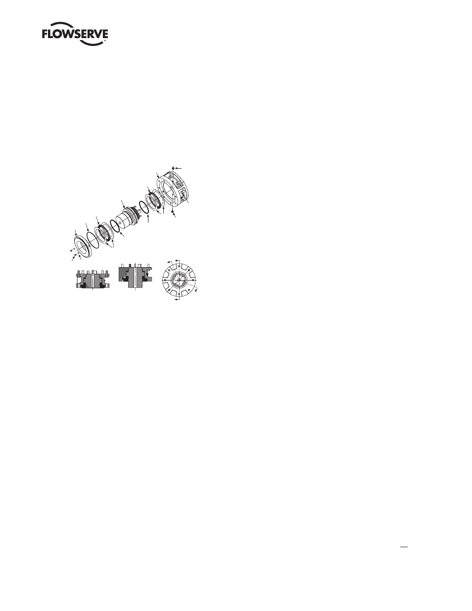
Figure 3.9 – Exploded view of thrust base (MX-140/MX-150 only)
Socket
head cap
screw s
Housing
Thrust
bearing
Quad ring
Thrust nut
Thrust
washers
Thrust
bearing
O-ring
Socket head
cap screw s
Washers
Thrust
pilot
Pipe plug
Pipe plug
Section A-A
View shown with
standard nut
Section B-B
View shown with
extended nut
A
B
B
A
Quad ring
Thrust
washers
3.2 Mechanical Installation Onto Valve or Gearbox
NOTE: Refer to MX Maintenance and Spare Parts bulletin (LMENIM2314) for more detailed instructions.
Before installing the actuator onto a valve or gearbox, check the following to ease installation:
• Verify that mounting flange is suited dimensionally to mate with the actuator base. Ensure that it is perpendicular to
the valve stem or gearbox input shaft.
• Ensure the stem nut mates with the valve stem or input shaft. For screwed nuts, it is advisable to run the stem nut
down the entire length of the stem to check for tightness. Keyed or splined shafts should exhibit a smooth, sliding fit
with the key installed.
• Ensure there is adequate engagement of the stem nut with the valve stem or input shaft when mounted. Generally, the
minimum length of engagement is 1.5 times the diameter of the stem.
• Verify that mounting studs or bolts are the correct length to suit the thickness of the mounting plate.
• Verify hardware specifications for English style:
• Socket head cap screw per ASTM A 574 and ANSI 18.3.
• Hex head cap screw per SAE J429 Grade 5.
• Verify hardware specifications for metric style: hex and socket head cap screws per Property Class 12.9.
• Clean and lubricate the valve stem or input shaft.
• Ensure adequate lifting facilities and slings are available at the installation site.
NOTE: Do not use the handwheel to lift the actuator.