Grounding instructions – MicroE Mercury II 6000V User Manual
Page 14
Page 14
Section B - Sensor Head Installation, Alignment and Calibration
Grounding Instructions -
Mercury
II
™
6000
C1.0
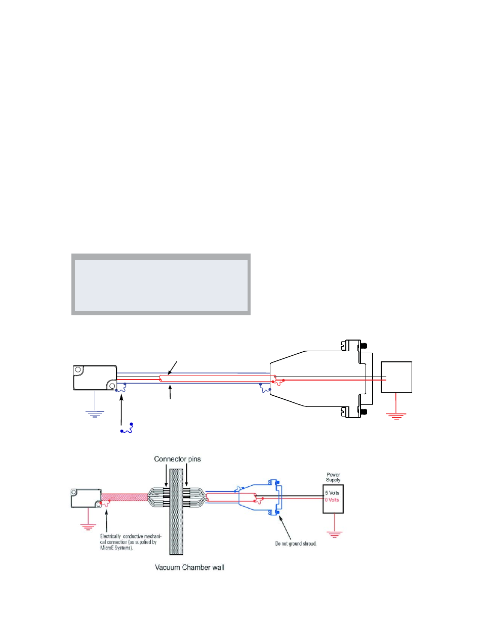
Grounding Instructions
For Mercury
II
6000 encoder systems to operate
reliably, it is essential that the sensor and cable shield
are grounded properly according to the following
instructions. The diagrams below show how to make
the connections when the encoder's connector is
plugged into the customer's controller chassis. If a
customer-supplied extension cable is used, it should be
a double shielded cable with conductive connector
shells and must provide complete shielding over the
conductors contained within it over its entire length.
Furthermore, the shields should be grounded at the
connection to the controller chassis the same way as
the encoder connectors in the diagrams below.
NOTE:
For best performance, isolate the encoder outer
shield from motor cable shields and separate the
encoder cable as far possible from motor cables.
Sensor mounted with good electrical
contact to a well-grounded surface
(preferred)
C
C1
1..1
1..1
1
15-pin D-sub connector grounding:
The encoder's connector shell must
be in intimate, electrically conductive
contact with the customer-supplied mating
connector, which must be isolated from the
controller's ground. If a customer-supplied
shielded cable connects the encoder to
the controller, then the outer shield on the
customer-supplied cable must be isolated
from the controller's ground.
C
C1
1..1
1..2
2
The sensor mounting surface must have a
low impedance (DC/AC) connection to
ground. The encoder sensor mounting
surface may have to be masked during
painting or anodizing to insure good
electrical contact with the sensor.
5 Volts
0 Volts
Electrically conductive
mechanical connection
(as supplied by MicroE Systems).
POWER
SUPPLY
INNER SHIELD:
Insulated from outer shield, sensor case, and
connector housing. Connected to circuit common
internally as supplied by MicroE Systems
OUTER SHIELD: Connected to
sensor and connector housing