Pushbutton setup alignment, Sensor head alignment – MicroE Mercury II 6000V User Manual
Page 8
Page 8
Section B - Sensor Head Installation, Alignment and Calibration
Sensor Head Alignment -
Mercury
II
™
6000 Models
B2.1
MII6000 Pushbutton Setup -
Sensor Alignment
Make sure that the 5VDC power input is
disconnected. Connect the MII6000 encoder to the
SmartPrecision Alignment Tool. Insert the 5VDC
power connector and apply power.
B
B2
2..1
1..1
1
To enter Alignment Mode, push and release
the Cal. button quickly (within a second).
The limit LED’s will begin to blink slowly.
B
B2
2..1
1..2
2
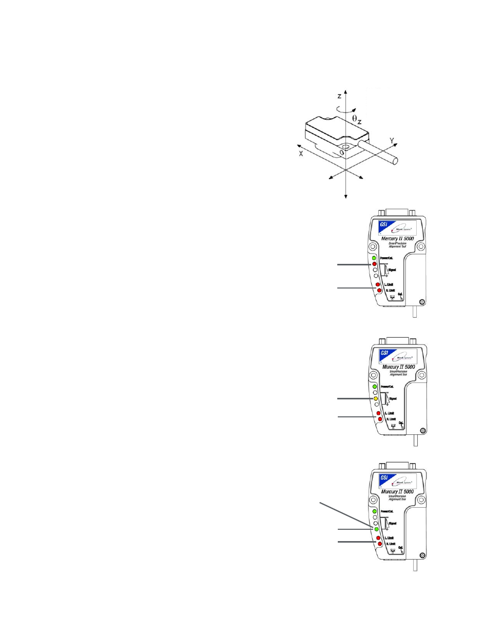
Align the sensor by slowly sliding the sensor
on its mounting surface in the Y or
θ
z
directions until the green Signal Strength
LED is illuminated. Tighten the sensor
mounting screws (0.37Nm [3.3 inch-lbs.]
maximum torque).
B
B2
2..1
1..3
3
Move the senor over the index mark and
confirm that the green Signal Strength LED
blinks. (If the green Signal Strength LED
does not blink when the sensor passes over
the index, loosen the mounting screws and
repeat the alignment procedure.)
B
B2
2..1
1..4
4
Move the sensor over the entire length of
the scale. If the green signal strength LED
remains illuminated over the entire length of
travel (the yellow and red LED’s do not
illuminate), proceed to the next step.
Otherwise, clean the scale and try again. If
cleaning the scale is not successful, loosen
the sensor mounting screws and repeat the
alignment procedure.
B
B2
2..1
1..5
5
Push and release the Cal. button quickly to
exit Alignment Mode. The limit LED’s will
stop blinking.
To align the
sensor move it
in the Y or
θz
directions
Improper
Alignment LED (red)
Limits LEDs blinking (in
Alignment Mode)
Limits LEDs blinking (in
Alignment Mode)
Limits LEDs blinking (in
Alignment Mode)
Improved Alignment
LED (yellow)
Proper Alignment LED
(green)
Optimum Alignment
LED (bright green)
Z
Y
X
θ
z