Sensor head installation – MicroE Mercury II 6000V User Manual
Page 6
Section B - Sensor Head Installation, Alignment and Calibration
Page 6
Sensor Head Installation
B1.1
Install the sensor on the mounting surface referencing
the appropriate datum surface as shown on the
Interface Drawing. Use two M-2 screws to loosely
affix the sensor.
Benching pins may be used to locate the sensor if the
system's mechanical tolerances are adequate. Refer to
the Interface Drawing for recommended locations and
heights of pins.
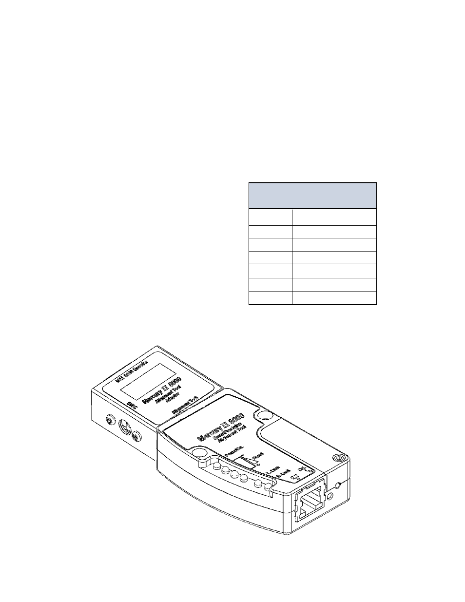
Mercury
II
Sensor Alignment Tolerances
Axis
Alignment Tolerance
X
Direction of Motion
Y
± 0.20mm
Z
± 0.15mm
θ
X
± 1.0°
θ
Y
± 1.0°
θ
Z
± 2.0°
B1.0
Verify Sensor Mounting Surface Height
Verify that the vertical distance between the reference
surface of the sensor and the top of the scale is
as follows:
Tape scale after blue protective film is removed:
3.09 mm +/-0.13
Linear or rotary glass scales: 2.93 mm +/-0.13
Check the height at a location on the scale where
there are no index or limit markers.