Vav/zone controllers – Orion System OE392-10 System Manager TS User Manual
Page 50
Zone
Zone
VAV/Zone Controllers
SMTS Technical Guide
50
Viewing VAV/Zone Status Screens and Enabling Alarms
Viewing VAV/Zone Status Screens
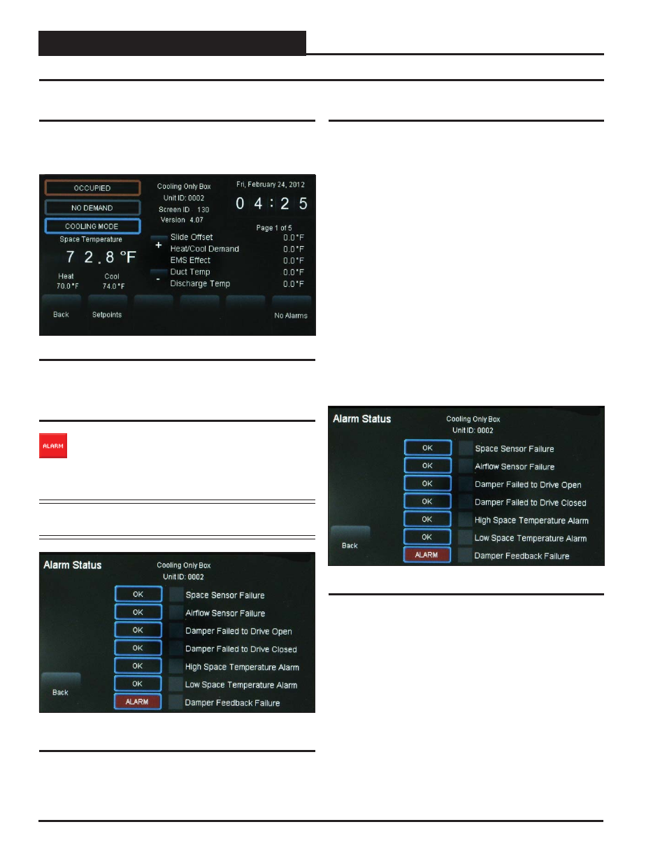
Figure 39 depicts a VAV/Zone Controller Status Screen. Notice that the
controller is identifi ed by loop number and unit number - in this case,
0101 represents Loop 1, Unit 1.
Figure 39: VAV/Zone Controller Status Screen
Viewing Alarm Status
To view alarm status, touch the
< ALARM>
button on the
unit’s Status Screen located at the right of the temperature
display. See Figure 39. The Alarm Status Screen will display.
See Figure 40. Only a Level 3 user has the option to enable
or disable each type of alarm.
NOTE:
The red
<ALARM>
button only appears on the screen
if the unit has an active alarm condition.
Figure 40: VAV/Zone Controller Alarm Status
Screen
Figure 41: VAV/Zone Controller Alarm Screen
Enabling/Disabling VAV/Zone Alarms
Alarm confi guration is accessed by touching the
<ALARM>
button
located at the far right bottom of the Status Screen. Only a Level 3 user
can confi gure alarms.
In addition to simply viewing alarms, the Alarm Status Screen can also
be used for enabling and disabling alarms that will be emailed or texted.
The emailing and texting feature will only work if Prism II is running
and has emailing capability.
The alarms must fi rst be confi gured using Prism II software. See the
Appendix in this guide for instructions.
Once the alarm settings have been established in Prism II, the settings
you choose in the Alarm Status Screen will be stored in the controller
so that you will not have to reconfi gure the alarms for that controller in
Prism II. Once confi guration is complete, Prism II does not have to be
running in order to view alarms on individual Alarm Status Screens in
the System Manager TS. However, as mentioned previously, Prism II
does have to be running for emailing or texting alarms to occur.
To enable an alarm, simply touch the grey square to the left of the alarm.
A white box designates that the alarm is enabled. To disable the alarm,
simply touch the square again.
In the example above (Figure 41), there is an ALARM, designated by
the word ALARM in red linear to Damper Feedback Failure. If there is
no alarm condition, the word OK appears in a box linear to each alarm .