Figure 3.4 polarization control, Rc2000 – Research Concepts RC2000A User Manual
Page 25
RC2000A Dual Axis Antenna Controller Chapter
3
Installation/Setup
25
4. When the feed has been centered in its range of travel, connect the ohm meter between the wiper
and one of the other terminals of the pot. Rotate the shaft of the pot until the resistance readfrom
the ohm meter is one half of the value of the pot's total resistance (obtained in step (1)).
5. Tighten the allen screw and verify that the pot is properly centered by performing the procedure
above entitled "Verifying Pot Center Position".
Replacement Potentiometer
The biggest problem encountered when using potentiometers in an outdoor application is moisture.
When moisture gets past the shaft seal on the pot, it will cause inaccurate readings and can eventually
lead to failure. The Contelec model PD2205, 5K ohm, 5 turn device has excellent environmental
characteristics. It is available from Novotechnik, Marlborough, MA, (508) 485-2244.
When replacing a pot on an existing feed (controlled via either the RC2KPOL or RC2KHPP options), the
resistance value of the potentiometer is not that important. It is necessary that the replacement pot
have either the same number of turns or a greater number of turns than the original pot. If the
replacement pot has a greater number of turns, there will be somewhat less resolution available in the
measurement of polarization position. When a potentiometer is replaced, the sensed polarization
positions which correspond to the satellite's horizontal and vertical positions will change.
Configuring the Controller for Optional Feed Drives
Use the following procedure to configure the RC2000A for use with a 5-40V DC polarization motor.
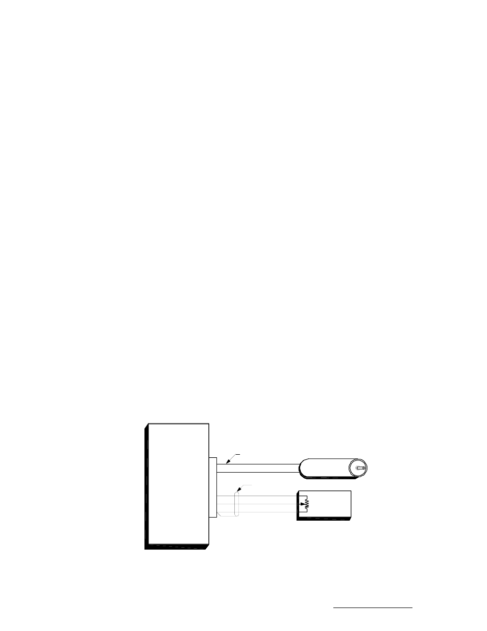
1. Connect the polarization/sensor assembly as shown in figure 3.4. Note that shielded cable is
required for the sensor and that the shield MUST be connected to the GROUND terminal (1) at the
back of the controller and MUST NOT be connected to anything at the antenna. Research
Concepts, Inc. can supply cable for installation. RCI part number CBL-2_16-3_22A contains 2 16
gauge conductors for carrying the motor drive current and a shielded triple with a drain wire in a
single UV resistant-direct burial jacket. Contact RCI for details.
2. The CONFIG mode item Rotating Feed Present? must be set to YES (1). Activate CONFIG mode
and use the SCROLL DOWN key to bring up the Rotating Feed Present? item and key in a 1
followed by the ENTER key. (If the Rotating Feed Present? item is not accessible in CONFIG mode,
the Expert Access Flag has been reset. If this occurs, perform a system reset as described in
section 3.1.)
3. When the controller is configured to work with a 24 volt polarization motor, the polarization position
may be optionally displayed in an angle format. For this part of the installation procedure, the angle
display feature must be disabled. To verify that the angle display feature is disabled, go to the
CONFIG mode Pol Angle Display item. If this feature is not disabled, key in a 0 at the Pol Angle
Display prompt followed by the ENTER key.
12 or 24VDC
POL. MOTOR
(must specify)
1
2
3
SENSOR REFERENCE
SIGNAL
SIGNAL RETURN
4
5
J4
POL. DRIVE(1)
POL. DRIVE(2)
18-22 AWG, SHIELDED
18-20 AWG, TWISTED
5K
POTENTIOMETER
SENSOR
RC2000
Figure 3.4 Polarization Control
Research Concepts, Inc. • 5420 Martindale Road • Shawnee, Kansas • 66218-9680 • USA www.researchconcepts.com