5 reset mode, Reset mode – Research Concepts RC2000A User Manual
Page 36
36
RC2000A Dual Axis Antenna Controller
Chapter 4
Modes
ordered with either of the satellite lists. The west set of satellites is appropriate for antenna sites with
western longitudes and the east set is appropriate for eastern longitudes.
4.5 RESET
Mode
The RESET mode is used to display azimuth and elevation drive fault conditions and re-enable the
drive outputs in the event the microcontroller has disabled an axis. When RESET mode is activated,
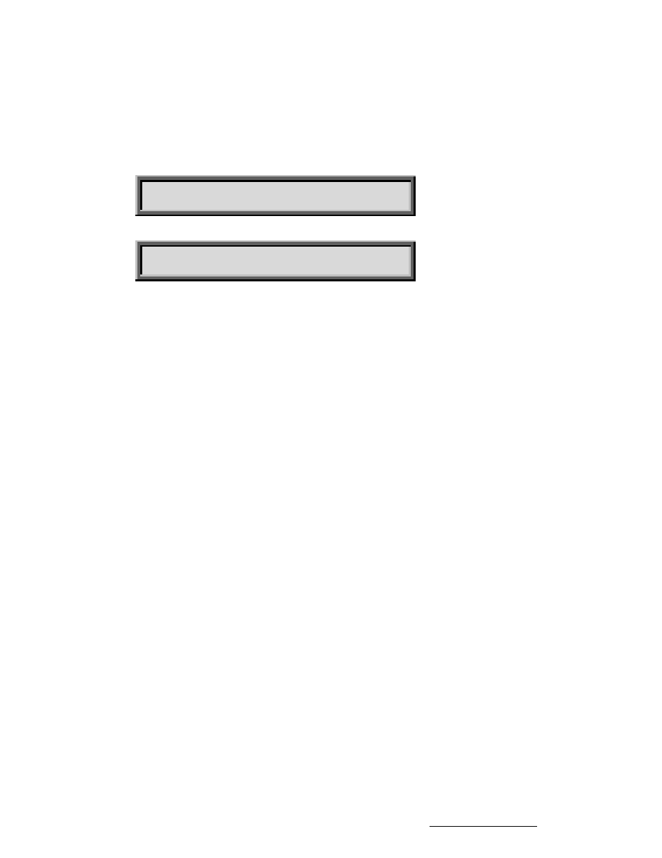
one of the following screens will be displayed.
AZ: OK EL: OK RESET
RESET AXIS: 1-AZ, 1-E
AZ: OK EL: OK PL: OK RESET
RESET AXIS: 1-AZ, 2-EL, 3-POL
The first screen will be displayed if a polarotor is present in the system and the second screen will be
displayed if the RC2KPOL or RC2KHPP options are installed to control motorized feeds with
potentiometer feedback.
The status of each axis is displayed after the appropriate banner (AZ:, EL:, or PL:) on the top line of the
LCD. If a fault exists for an axis, no movement may occur about that axis until that axis is reset. Use
the 1 key to reset the azimuth axis, the 2 key to reset the elevation axis, and the 3 key to reset the
polarization axis. Note that polarization status is displayed and polarization resets are possible only if
the optional rotating feed interface is installed.
Here are the status messages which may be displayed:
OK
Indicates that no fault conditions are active for the axis (azimuth, elevation, or polarization).
JAMMED
Indicates that the antenna was commanded to move about the axis and no movement was
detected by the controller. This indicates either that the antenna did not move when
commanded to do so, or the sensor failed and the controller was not able to detect any
movement (azimuth, elevation, or polarization).
RUNAWAY
The drive was deactivated because the processor sensed movement for a drive which was not
commanded to move. This error is rarely caused by an actual runaway condition (the antenna
moving on its own). This error is usually due to a faulty sensor or noise pickup due to the
sensor shield not being connected properly. See Chapter 3 for proper shield connection
instructions (azimuth and elevation).
DRIVE
The axis was deactivated due to an over-current condition (azimuth, elevation, and high current
polarization axis). This error condition can be detected only if the RC2KHPP option is present
in the system (software version 1.51). It will not be detected for the RC2KPOL option (software
version 1.50).
SENSOR
This error will occur if the antenna commands a polarization movement, and movement is
detected in the wrong direction. Note that a polarization jammed condition will occasionally
Research Concepts, Inc. • 5420 Martindale Road • Shawnee, Kansas • 66218-9680 • USA www.researchconcepts.com