Research Concepts RC2000A User Manual
Page 82
82
RC2000A Dual Axis Antenna Controller
Appendix F
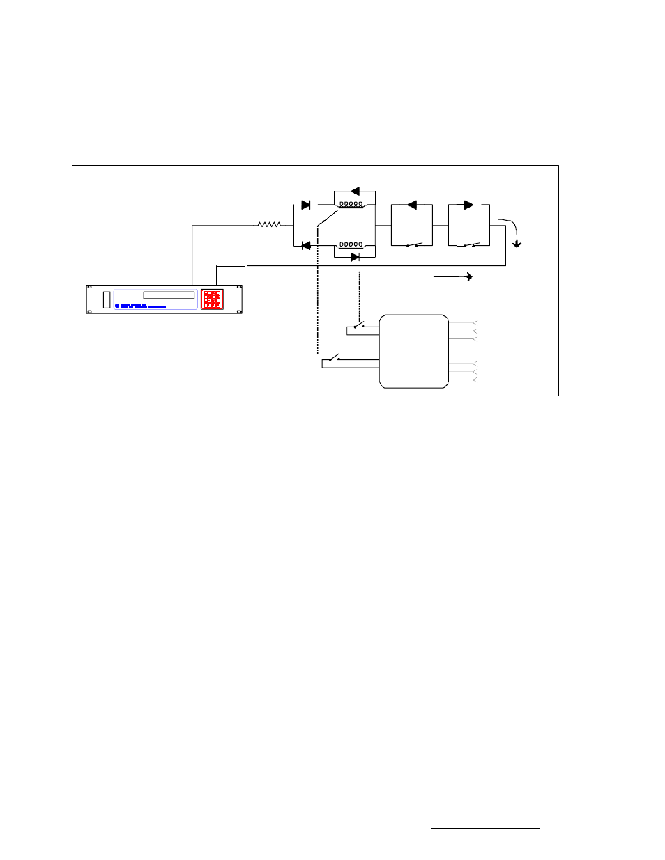
AC or Large DC Motors
Note that the scheme shown in Figure 1 does not support slow speed movement. With 36-volt motors,
the RC1000 and RC2000 vary the motor speed by rapidly switching the 36-volt antenna drive signals
off and on - which gives an average voltage of less than 36 volts. If this signal is applied to the circuit of
Figure 1, the relays would chatter. On the RC2000, slow speed movement may be disabled by setting
the azimuth and elevation slow speed codes to 254. On the RC1000, slow speed movement is disabled
by setting the slow speed index to the highest possible value.
D4
D3
Li m i t Swi t c h
AZ CW
AZ CCW
Li m i t Swi t c h
AZ CW Cu r r en t
AZ CCW Cu r r en t
PO WER
CON T ACT OR
AZ CW Co n t ac t
Cl o s u r e
AZ CCW Co n t ac t
Cl o s u r e
2 30 Vol t s AC
( 3 - ph a s e)
i n p u t
t o Az i m u t h
3 - p h a s e
AC Mo t o r
AZ CCW Re l a y
Co i l
AZ CW Re l a y
Co i l
D1
D2
3 6 Vo l t s D C
o u t p u t
E
AZ1
AZ2
R
RC2 0 00 An t en n a Con t r o l l e r
Vol t a ge Dr o p p i n g R es i s t or
( t o m at c h t h e ou t p u t o f t h e RC2 0 00
t o t h e Re l a y Co i l s )
T h e l i m i t s w i t c h e s o p e n
w h e n t h e l i m i t i s r ea c h ed .
, R.
When controlling AC or large DC motors with either the RC1000 or RC2000, it may be necessary to
change the controller's ANTI-REVERSAL DEADBAND, COAST, RETRY COUNT, and MAXIMUM
POSITION ERROR parameters. These parameters control the movement of the antenna.
When the antenna has been moving in one direction, it must be allowed to come to a complete stop
before it is commanded to move in the opposite direction, or position pulses may not be accumulated
properly. The ANTI-REVERSAL DEADBAND specifies the minimum number of milliseconds between
antenna movements in opposite directions. On the RC2000A the user may specify four deadbands,
azimuth fast, azimuth slow, elevation fast, and elevation slow. For the RC2000C the user can specify
two deadbands - Az/El fast and Az/El slow. When the circuit of Figure 1 is used, the fast and slow
deadbands for a given axis should be set to the same value.
When the antenna is performing an automatic move to a target position, the antenna drive signals are
released before the antenna reaches the target position. The idea is that the drive signals are released
and the antenna coasts into position. The COAST parameters specify the number of position counts
before a target position is reached where the drive signals are released. There are unique COAST
parameters for each axis on the RC2000.
When the antenna is performing an automatic move, the controller will make a number of attempts to hit
the target position. The RETRY COUNT parameter specifies how many attempts the controller will
make to reach the target position. The MAXIMUM POSITION ERROR parameter specifies the
maximum allowable error about the target position. If the antenna comes to a stop within maximum
position error counts of the target position, the controller will not attempt to make another move to get
the antenna closer to the target position.
On the RC2000 these parameters may be set by the user via CONFIG mode. On the RC1000 these
parameters are programmed into the controller's EPROM memory and can only be changed at the
factory.
Research Concepts, Inc. • 5420 Martindale Road • Shawnee, Kansas • 66218-9680 • USA www.researchconcepts.com