4 geo elevation position, 5 azimuth and elevation slow speed codes, 6 azimuth and elevation angle display – Research Concepts RC2000A User Manual
Page 40
40
RC2000A Dual Axis Antenna Controller
Chapter 4
Modes
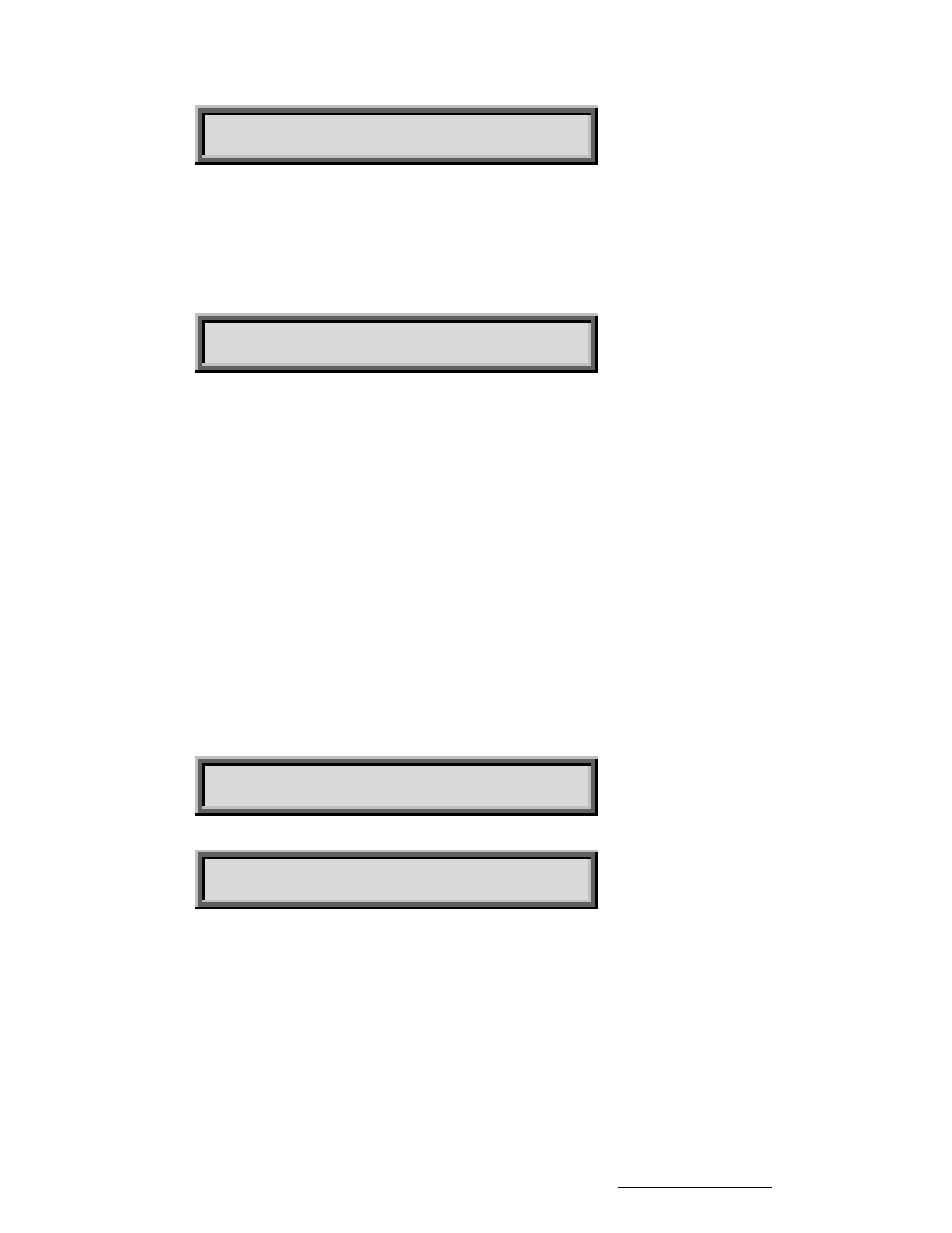
COMM BAUD RATE (HUNDREDS):96 CONFIG
3, 6, 12, 24, 48, 96 ENT,BKSP,SCRLL ^v
4.10.4 Geo Elevation Position
The Geo Elevation Position is defined for modified polar type antenna mounts. For a modified polar
mount this is the elevation position where the antenna will track the geo-stationary satellite arc with only
azimuth movements. See section 3.4.3 for more information on this feature. This value is normally set
via LIMITS mode. If the value of this item is set to zero, display of elevation position relative to the Geo
Elevation Position is disabled. The Expert Access Flag must be set to obtain access to this parameter
via CONFIG mode.
GEO ELEV POSITION: 0 CONFIG
0-DISABLE ENT,BKSP,SCRLL ^v
To assign a meaningful value to this parameter, use the following procedure:
1. Adjust the mount so that it will track the geostationary arc with only azimuth movement.
2. Go to CONFIG mode and set this parameter to zero (0).
3. In MANUAL mode, determine the elevation value at which the mount will track the geostationary
satellites with only azimuth movement.
4. Go to CONFIG mode and set the Geo Elev Position to the elevation value found in step 3.
4.10.5 Azimuth and Elevation Slow Speed Codes
These CONFIG items can be used to set the azimuth and elevation slow speed codes. Normally, these
parameters are adjusted interactively via the AZIM SLOW and ELEV SLOW modes. Please refer to
sections 3.5 and 4.8 for more information on the slow speed system. The range of values for these
parameters is from 1 to 254. Higher numbers give faster speeds. (For a given axis, a slow speed code
of 254 will disable the slow speed system for that axis - all movement will occur at fast speed.) For
most motor/sensor combinations, a slow speed code in the range of 140 to 175 is appropriate. If the
slow speed codes are changed, test the slow speed system to insure that the selected values yield
reasonable results. Access to these CONFIG mode items are allowed only when the Expert Access
Flag is set.
AZIM SLOW SPEED 0-254:253 CONFIG
ENT,BKSP,SCRLL ^v
ELEV SLOW SPEED 0-254:253 CONFIG
ENT,BKSP,SCRLL ^v
4.10.6 Azimuth and Elevation Angle Display
The RC2000A has the ability to display azimuth and elevation position in an angle format. This feature
can greatly facility the process of locating satellites for systems which use an elevation over azimuth
type antenna mount. Please see section 3.7 for more information on how to enable and calibrate this
feature. Access to these CONFIG mode items allowed only when the Expert Access Flag is set.
Briefly, to calibrate the angle display feature, the user locates two satellites and records their azimuth
and elevation position count values. The scale2.exe PC program (for IBM compatibles - shipped with
each controller) is then used to calculate azimuth and elevation scale factors. These scale factors are
entered into controller via the CONFIG mode items described in this section. The scale2.exe program
Research Concepts, Inc. • 5420 Martindale Road • Shawnee, Kansas • 66218-9680 • USA www.researchconcepts.com