ARM Electronics JDVR User Manual
Page 9
B e s t p ic tu re q u a lity D V R
JP E G 2000 S tan d- alo ne D VR
8
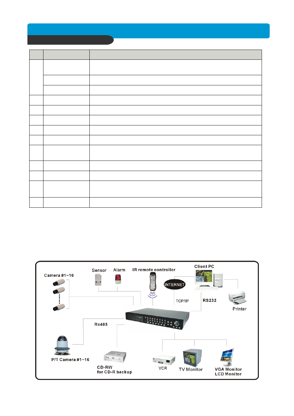
3-1. Installation Configuration
CHAP. 3 Installation
CHAP.3 Installation
Power ON/OFF
POWER
SWITCH
10
11
9
8
7
6
5
4
3
2
1
MONITOR
Output
LOOP Output
CAMERA Input
RS-232C
ETHERNET
VGA
SENSOR Input
Connection with PTZ Camera or other external device using RS 485
interface (Pin 1: D- / Pin 2: D+)
RS 485
USB Device
DC Power
VCR Output
Firmware upgrade by connecting PC with latest firmware to USB port
DC power input (DC12V, 10A )
Connection with VCR for analog backup
Connection with Composite Monitor
Camera loop out
Connection with camera
Connection to external device as PC using RS-232C to control the DVR
Connection to ETHERNET device
Connection to VGA Monitor (CRT type or TFT LCD monitor)
Sensor input terminal
Relay out terminal
RELAY Output
Function
Name