Module front rj-45 connector – Grass Valley 2000NET v4.0.0 User Manual
Page 14
14
2000NET Instruction Manual
Installation
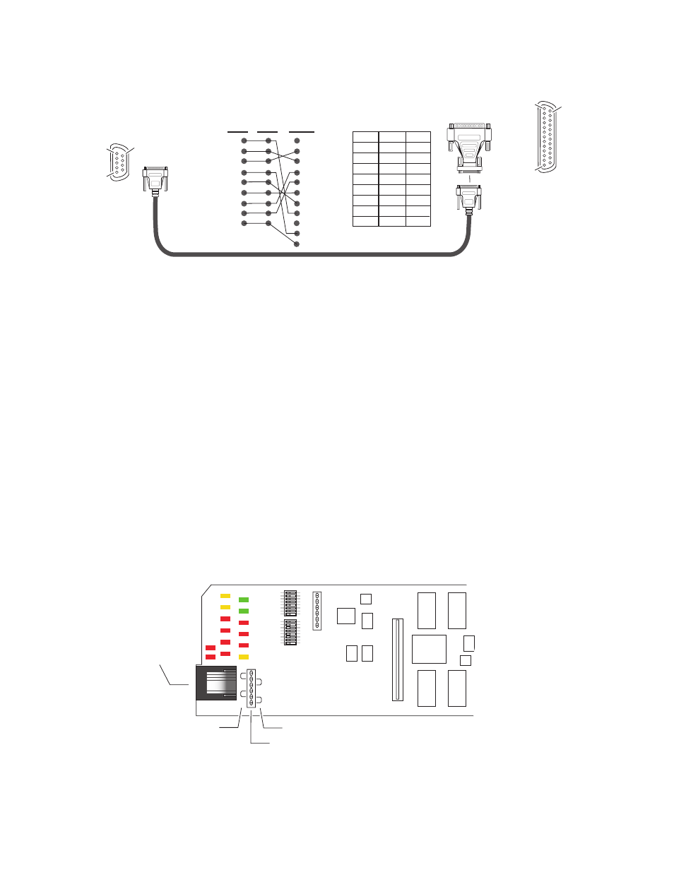
Figure 9. DB-9 Cable and DB-25 Cable Adaptor Pinout
Module Front RJ-45 Connector
When the 2000NET module is installed in a 1 RU 2000T1 frame, the dual
purpose RJ-45 connector on the front of the 2000NET module is used as the
Serial Configuration port for the module. The RJ-45 connector is configured
using the jumper positions shown in
. Use the RS-232 (
DIAG
)
jumper positions when connecting to a PC for initializing the 2000NET
module. The
Front Panel
jumper configuration is for future use.
CAUTION This is not an Ethernet port. Damage can result from connecting Ethernet
equipment to this connector.
In the three rackunit 2000T3 frame, with the jumpers set in the DIAG posi-
tion, the RJ-45 connector is in parallel with the Serial Configuration port on
the back of the frame (J101).
Note
In the 2000T3 frame, the module front connector and rear frame connector
cannot be used at the same time.
Figure 10. Dual Purpose RJ-45 Connector and Jumpers
1
2
3
4
5
6
7
8
9
1
2
3
4
5
6
7
8
9
8
3
2
20
7
6
4
5
22
8046 -19r2
25-pin
25-pin
9-pin
9-pin
9-pin
Note: Only Tx, Rx and pin 5 (9-pin) to pin 7 (25-pin) are required.
1
2 Tx
3 Rx
4
5
6
7
8
9
20
22
1
Tx 2
Rx 3
4
5
6
7
8
9
9-pin
DB-25
Female
DB-25
Female
Pinout
DB-9
Male
Pinout
DB-9
Female
Pin 5
Pin 1
Pin 9
Pin 1
Pin 13
Pin 14
Jumper J9
Front Panel functions (currently not used)
RS-232 configuration
functions (DIAGnostics)
RJ-45 Connector
8046 -29r1