Installation, Module placement in the kameleon frame – Grass Valley 2000NET v4.0.0 User Manual
Page 9
2000NET Instruction Manual
9
Installation
Installation
This section describes placing the module in the 2000 Series Kameleon
frame and cabling the communications ports. Procedures for power-up,
DIP switch settings, and network configuration of the module are
described in following sections.
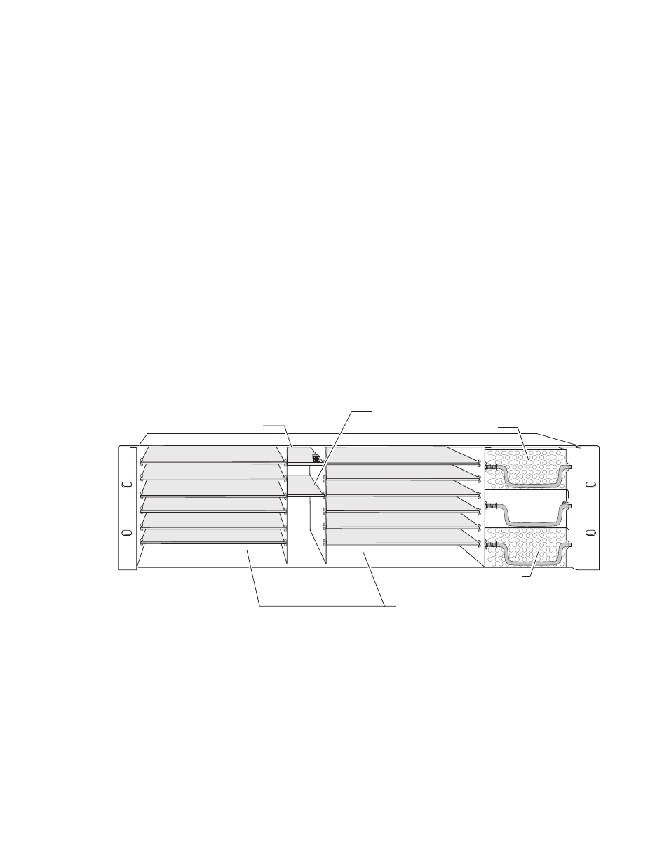
Module Placement in the Kameleon Frame
In a 3 RU frame, there are two rows of six front media module slots in the
frame to accommodate either analog or digital media modules. Between
these rows are slots for the 2000NET and 2000GEN Frame Reference mod-
ules. Refer to
The three slots on the right side of the frame are allocated for the power
supply sleds and the optional fan module. For additional information con-
cerning the Power Supply module, refer to the 2000 Series Frame Instruction
Manual.
Slot number 13 (top middle) is allocated for the 2000NET module.
Figure 3. 2000T3NG Frame Front Module Locations
(2)
(3)
(4)
(5)
(6)
(7)
(8)
(9)
(10)
(11)
(12)
(15)
(13)
(1)
8046_03r1
2000NET Network Interface Slot (13)
2000GEN, Reference Distribution Slot (15)
Main Power Supply Slot (18)
Secondary Power
Supply Slot (20)
Front Media Slots (1-12)
Fan Sled
Slot (19)