3 main circuit wiring, 1 main circuit terminals – Yaskawa Sigma-5 User Manual: Setup for Linear Motors User Manual
Page 104
Advertising
3 Wiring and Connection
3.3.1 Main Circuit Terminals
3-20
3.3
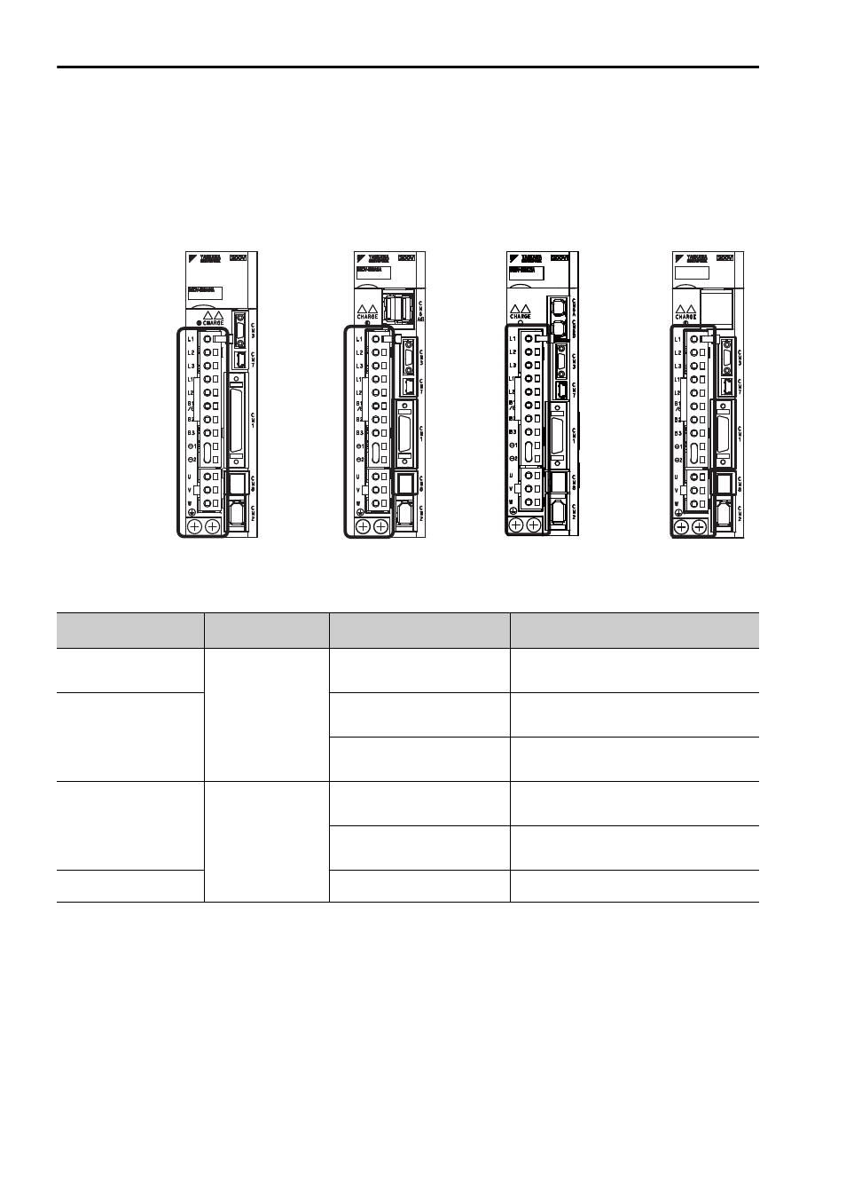
Main Circuit Wiring
The names and specifications of the main circuit terminals required for trial operation
are given below.
3.3.1 Main Circuit Terminals
Analog Pulse Models
M-II Models
M-III Models
Command Option
Attachable Types
SGDV-1R6AE1A
Terminal Symbols
Name
Model SGDV-
Description
L1, L2
Main circuit
input terminals
F
Single-phase 100 to 115 V,
+10% to -15% (50/60 Hz)
L1, L2, L3
A
Three-phase 200 to 230 V,
+10% to -15% (50/60 Hz)
D
Three-phase 380 to 480 V,
+10% to -15% (50/60 Hz)
L1C, L2C
Control power
input terminals
F
Single-phase 100 to 115 V,
+10% to -15% (50/60 Hz)
A
Single-phase 200 to 230 V,
+10% to -15% (50/60 Hz)
24 V, 0 V
D
24 VDC,
±
15%
Advertising