Three-phase, 400 v, 3) typical main circuit wiring examples – Yaskawa Sigma-5 User Manual: Setup for Linear Motors User Manual
Page 108
3 Wiring and Connection
3.3.2 When Using a Standard Power Supply Input (Single-phase 100 V, Three-phase 200 V, or
Three-phase 400 V)
3-24
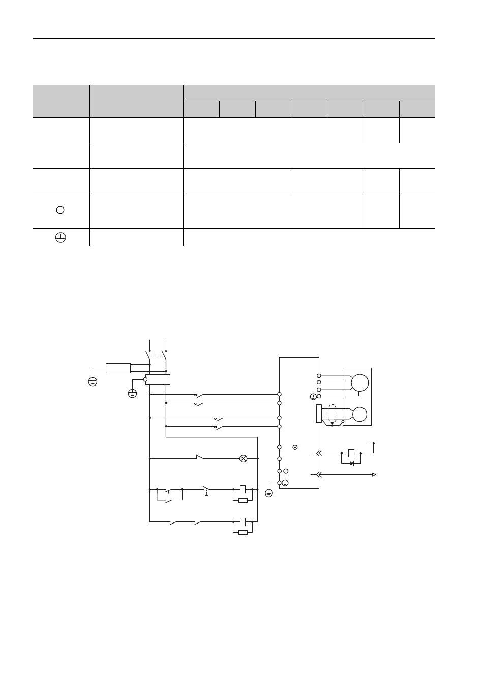
Three-phase, 400 V
(3) Typical Main Circuit Wiring Examples
The following wiring examples show the
Σ-V Series SGDV SERVOPACK
(Analog pulse model).
Single-phase 100 V, SGDV-F (SGDV-R70F, R90F, 2R1F, 2R8F)
Note: For M-II model, M-III model, and command option attachable type SERVOPACKs, the
pin number of ALM+ terminal is CN1-3, and that of ALM
− terminal is CN1-4.
Terminal
Symbols
Terminal Names
SERVOPACK Model SGDV-D
1R9
3R5
5R4
8R4
120
170
260
L1, L2, L3
Main circuit power
input terminals
HIV1.25
HIV2.0
HIV3.5
HIV
5.5
24 V, 0 V
Control power input
terminals
HIV1.25
U, V, W
Linear servomotor
connection terminals
HIV1.25
HIV2.0
HIV3.5 HIV5.5
B1/
, B2
External
regenerative
connection terminals
HIV1.25
HIV2.0 HIV3.5
Ground terminal
HIV2.0 or higher
L1
ENC
SERVOPACK
SGDV-
F
U
V
W
M
0 V
1Ry
+
−
31
32
1D
2KM
1KM
B2
L2
CN1
1QF
R
T
+24 V
B1/
3SA
(For servo
alarm display)
1Ry
1PL
1KM
2KM
1SA
Servo power
supply ON
Servo power
supply OFF
1KM
1Ry
1KM
2SA
1QF
1FLT
1KM
2KM
: Molded-case circuit breaker
: Noise filter
: Magnetic contactor (for control power supply)
: Magnetic contactor (for main power supply)
1Ry
1PL
1SA
2SA
3SA
1D
: Relay
: Indicator lamp
: Surge absorber
: Surge absorber
: Surge absorber
: Flywheel diode
L1C
L2C
ALM
ALM
1FLT