Yaskawa Sigma-5 User Manual: Setup for Linear Motors User Manual
Page 46
2 Installation
2.2.4 SGLC Linear Servomotors (Cylinder Type)
2-24
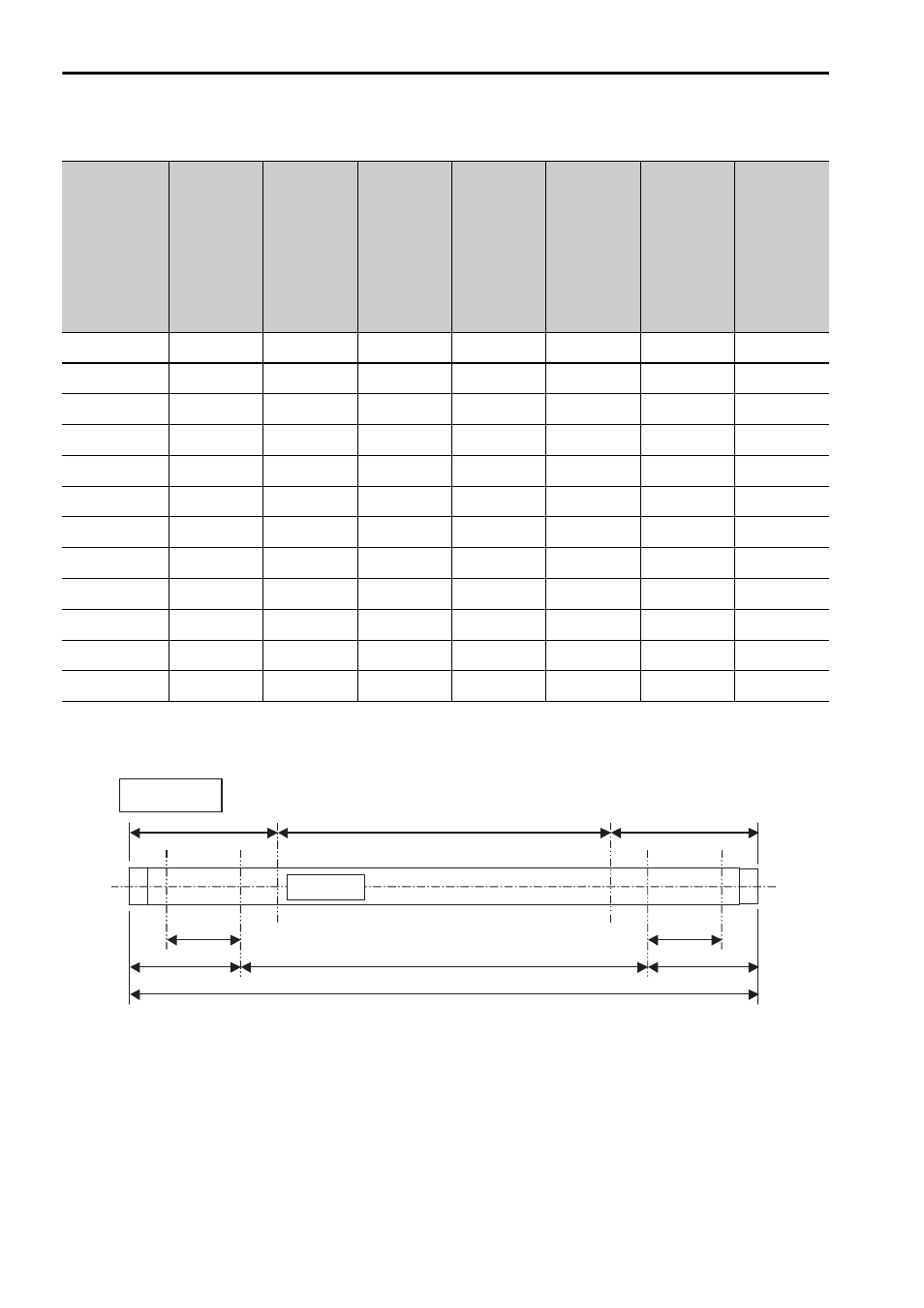
Table 2.1 Dimensions of the Magnetic Way (Selected models only)
Magnetic
Way
Model
SGLCM-
Total
Length
of Mag-
netic
Way L1
(mm)
Position
of
Support
Section
L2 (mm)
Driving
Range
of Coil
Assem-
bly
L3 (mm)
Length
of Sup-
port
Section
L4 (mm)
Range
outside
the
Guaran-
teed
Force *
L5 (mm)
Range
within
the
Guaran-
teed
Force
L6 (mm)
Range
outside
the
Guaran-
teed
Force *
L7 (mm)
D16300
300
± 1.6
30
240
25
37.5
± 0.3
225
± 1.2
37.5
D16510
510
± 2.5
45
420
40
52.5
± 0.3
405
± 2.1
52.5
D16750
750
± 3.0
45
660
40
52.5
± 0.3
645
± 2.5
52.5
D20350
350
± 1.6
35
280
30
45
± 0.3
260
± 1.2
45
D20590
590
± 2.5
50
490
45
60
± 0.3
470
± 2.1
60
D20870
870
± 3.0
50
770
45
60
± 0.3
750
± 2.5
60
D25450
450
± 1.6
45
360
37
57.5
± 0.3
335
± 1.2
57.5
D25750
750
± 2.5
60
630
52
72.5
± 0.3
605
± 2.1
72.5
D251110
1110
± 3.0
60
990
52
72.5
± 0.3
965
± 2.5
72.5
D32600
600
± 1.6
60
480
52
75
± 0.3
450
± 1.2
75
D321020
1020
± 2.5
90
840
82
105
± 0.3
810
± 2.1
105
D321500
1500
± 3.0
90
1320
82
105
± 0.3
1290
± 2.5
105
∗If a part of the moving coil is located within this range, predetermined characteristics cannot be satisfied.
Reference side
(mounting side)
L5
L4
L2
L3
L1
L6
(L7)
(L2)
L4
Nameplate