3) magnetic attraction – Yaskawa Sigma-5 User Manual: Setup for Linear Motors User Manual
Page 43
2.2 Linear Servomotor Installation
2-21
2
Installation
(3) Magnetic Attraction
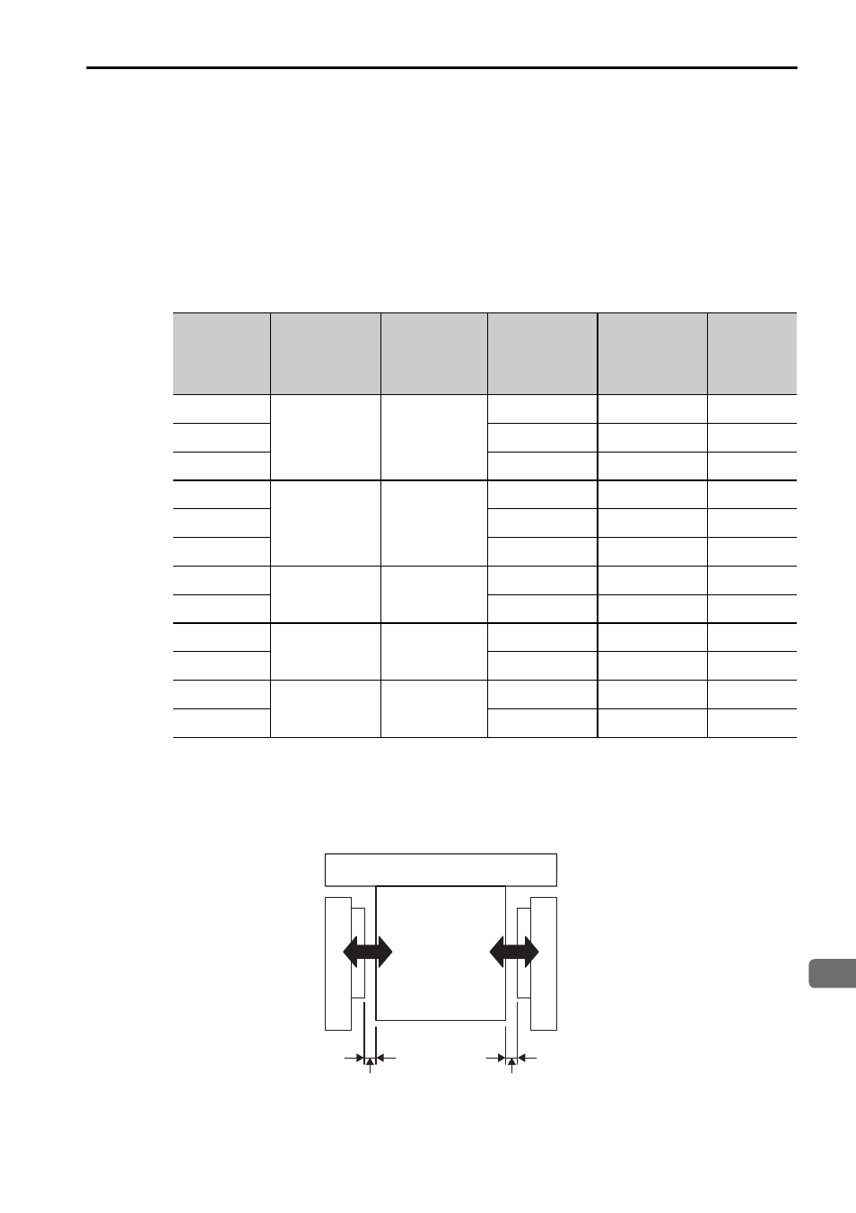
The linear servomotor is constructed of an opposing moving coil and magnetic way.
So, the magnetic attraction is offset when the air gaps between the moving coils and
the magnetic way are even.
However, achieving an even air gap is difficult due to the accuracy of the linear ser-
vomotor itself and the customer’s machine, and because of errors in the assembly of
the linear servomotor at installation. Consider the magnetic attraction values (calcu-
lated values) shown in the following table when designing the system.
∗1. Indicates an air gap when one side is +0.3 mm and the other side −0.3 mm relative to the
design values.
∗2. Indicates the magnetic attraction at maximum force.
∗3. The value in parentheses is the dimensions when the magnet protection cover is used.
Moving Coil
Model
SGLTW-
Air gap
G1
∗1
in mm
Air gap
G2
∗1
in mm
Magnetic
attraction
F1
∗2
(N)
Magnetic
attraction
F2
∗2
(N)
Attraction
difference
Δ
F
(N)
20A170
1.3
(1.1)*
3
0.7
(0.5)*
3
760
1030
270
20A320
1510
2040
530
20A460
2260
3050
790
35170
1.3
(1.1)*
3
0.7
(0.5)*
3
1330
1800
470
35320
2650
3570
920
35A460
4000
5400
1400
40400
1.7
(1.5)*
3
1.1
(0.9)*
3
4700
5900
1200
40600
7000
8700
1700
50170
1.3
(1.1)*
3
0.7
(0.5)*
3
1900
2600
700
50320
3750
5100
1350
80400
1.7
(1.5)*
3
1.1
(0.9)*
3
9200
11400
2200
80600
13600
16900
3300
Air gap
G1
Magnetic
attraction
F1
Moving coil
Magnetic way
Magnetic way
Magnetic
attraction
F2
Air gap
G2