3wiring and connection, 3 main circuit wiring 3-29 – Yaskawa Sigma-5 User Manual: Setup for Linear Motors User Manual
Page 113
3.3 Main Circuit Wiring
3-29
3
Wiring and Connection
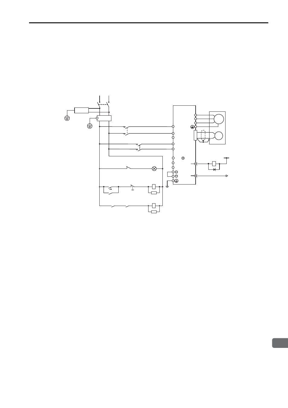
(4) Wiring Example with a Single-phase 200 V Power Supply Input
The following wiring example shows the
Σ-V series SGDV SERVOPACK
(Analog pulse model).
Single-phase 200 V Power Input Supported SERVOPACK Models
SGDV-R70A, -R90A, -1R6A, -2R8A, and -5R5A
Note: For M-II model, M-III model, and command option attachable type SERVOPACKs, the
pin number of ALM+ terminal is CN1-3, and that of ALM
− terminal is CN1-4.
1PL
1KM
2KM
1SA
2SA
L1
0 V
1Ry
1D
2KM
L3
B2
B3
L2
U
V
W
M
1QF
R
T
1FLT
+24 V
ENC
1
2
L1C
1KM
L2C
3SA
B1/
+
−
31
32
CN1
1KM
1Ry
1KM
ALM
ALM
1Ry
SERVOPACK
SGDV-
A
Servo power
supply ON
Servo power
supply OFF
1QF
1FLT
1KM
2KM
: Molded-case circuit breaker
: Noise filter
: Magnetic contactor (for control power supply)
: Magnetic contactor (for main power supply)
1Ry
1PL
1SA
2SA
3SA
1D
: Relay
: Indicator lamp
: Surge absorber
: Surge absorber
: Surge absorber
: Flywheel diode
(For servo
alarm display)