JBL Synthesis SDP-45 4K User Manual
Page 21
Basic Operation
JBL SYNTHESIS SDP-45
- 21 -
13
Trigger Input & Outputs
Four (4) 3.5mm two-conductor (Mono-Mini) phone jacks with the tip
being positive and the sleeve being negative.
The trigger input accepts from 3V to 12V DC to turn the SDP-45 on.
With no voltage the SDP-45 will go into standby. If no trigger cable is
inserted into the input then the front panel standby button will control
the power status. The front panel button will always be able to turn
on the SDP-45 regardless of trigger status, however if the SDP-45 is
turned on with the trigger, then the SDP-45 will only turn off with the
trigger.
Three (3) outputs that supply 12V DC trigger output. The three
outputs are per source selectable through the Setup Menu
configuration.
14
Infrared Remote Control Input
Accepts input of IR signals from infrared distribution equipment.
15
AES Digital Inputs
Two (2) 3 pin female XLR jacks for digital audio inputs conforming to the
Audio Engineering Society/European Broadcasting Union standard using
110 Ohm shielded twisted pair wire.
16
7.1 Analog Inputs (Unbalanced RCA)
Eight RCA jacks for connecting single-ended analog surround signals.
This source does not have any video assigned. The last used video
source will remain active when selecting this input. To select a video
source first select the active video source and then select the 7.1 or USB
input. If no video is required then do not first select a video source.
17
Balanced Analog Inputs (Stereo)
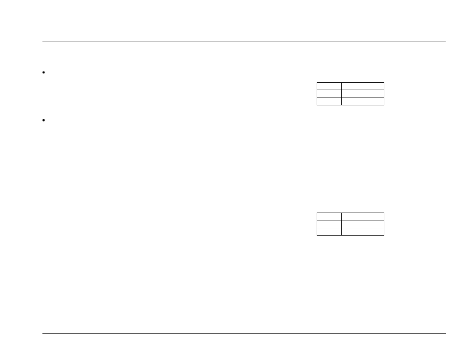
Two (2) pairs of balanced XLR-Female audio inputs. The XLR inputs use
the standard ―Pin 2 Hot‖ configuration.
XLR Pin
Signal
1
Ground/Shield
2
Signal +
3
Signal -
18
7.1 + Aux Outputs (Balanced XLR)
Eight (8) XLR-Male connectors provides analog audio output from the
Main Zone labeled Front L/R, Center, Subwoofer, Side L/R, and Rear
L/R are available.
An additional XLR-Male pair labeled AUX L/R is available and provides a
2-Channel downmix of the main 7.1 outputs. The AUX outputs can be re-
configured to provide an extra (duplicate) output for the Center and
Subwoofer signals. When used as a duplicate output the Left-Aux
becomes the Center and the Right-Aux becomes the Subwoofer. This
output is configured in the System setup menu.
XLR Pin
Signal
1
Ground/Shield
2
Signal +
3
Signal -
19
7.1 + Aux Outputs (Unbalanced RCA)
Eight (8) RCA connectors provides analog audio output from the Main
Zone labeled Front L/R, Center, Subwoofer, Side L/R, and Rear L/R are
available.
An additional RCA pair labeled AUX L/R is available and provides a 2-
Channel downmix of the main 7.1 outputs. The AUX outputs can be re-
configured to provide an extra (duplicate) output for the Center and
Subwoofer signals. When used as a duplicate output the Left-Aux
becomes the Center and the Right-Aux becomes the Subwoofer. This
output is configured in the System setup menu.