Fader number, Alias / label, Input meter – Logitek Electronic Systems Artisan User Manual
Page 27: Gain reduction meter, Logitek
Logitek
5
Operation
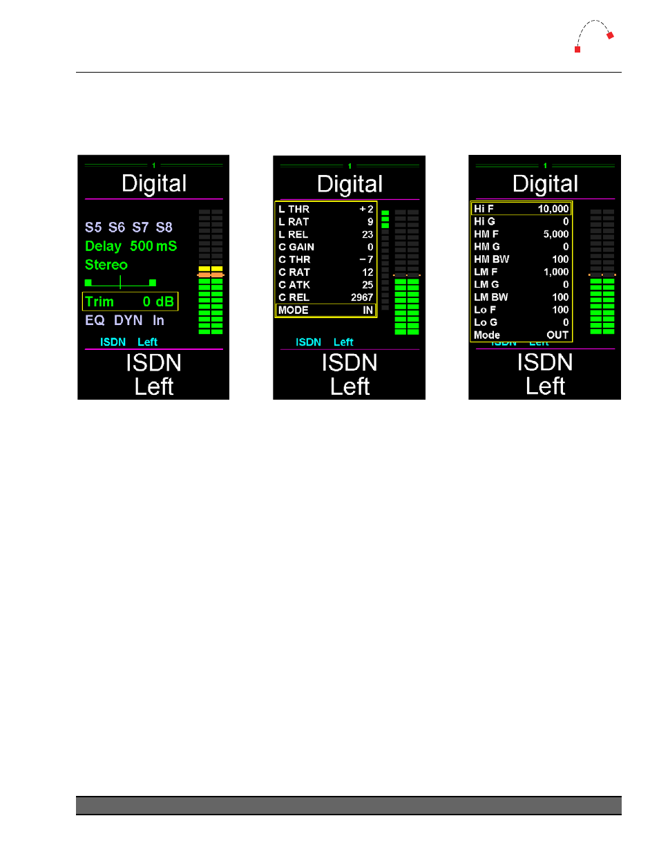
MTK-FADER (Fader Module) – Screens
The Fader Module has an LCD color screen shared between two faders. Illustrated below is the
section for a single fader. The Artisan is also supplied with vChange, a software tool which allows
the fader screen to be replicated onto a PC screen for larger display.
Figure 13 - Function Screen
Figure 12 - EQ Screen
Figure 14 - Dynamics Screen
Fader Number
Faders are numbered from left to right starting at 1.
Alias / Label
An Alias can be assigned to a source device and will be displayed on any fader that has that source
as an input. A Label can be written to a specific fader from a Trigger. Both can only be a maximum
of 8 characters on the Surface and are displayed at the top section of the Fader Screen. An Alias
can be 16-characters in length in vScreen, but only the first 8 characters display on the Surface.
¬
See the CommandBuilder manual for more information on Aliases and Labels.
Input Meter
Input level meters are provided for each fader by default (from the SA-DSP card). This meter can be
configured to be either pre-fader or post-fader. Post-fader is set by turning on BUS20 for that fader.
This setting can be set in the Init Trigger or changed as required in other Triggers.
Gain Reduction Meter
A gain reduction meter is provided for each fader. This meter only appears when Dynamics is
turned on, and shows the amount of gain reduction being applied by the compressor and limiter.
Logitek Artisan Reference Manual
25