Set default route, Set aux bus, Logitek – Logitek Electronic Systems Artisan User Manual
Page 60
Logitek
Appendix E
Additional Protocol Commands
Set Default Route
Used to set the default route for the IN / LAST buttons and Monitor Hotkeys. (v2.0 and later)
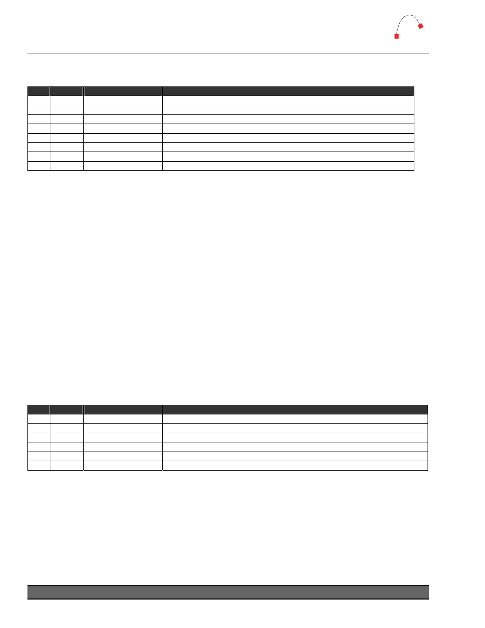
Seq
Byte
Description
Notes
1
<02>
Start byte
2
<06>
Bytes to follow
3
<AE>
Command = Set Effect
4
<d#>
Device Number
Device Number in hex (eg Fader number, St 1, St 2, Control Room, Offline Source)
5
<3E>
Type = Default Route
6
<b#>
Bus Number
<01> = LAST / IN button <10> to <13> = Monitor Hotkeys (16-19 decimal)
7
<sh>
Source High
Source Device high byte
8
<sl>
Source Low
Source Device low byte
The follow example will set the default route for the IN button on Port 1 Fader 1 (Device OB) to
Source Device
0100:
02 06 AE 0B 3E 01 01 00
TIP:
BUS37 must be turned ON for this device to enable the IN button to function as the
default route selector. If BUS37 is OFF, the IN button will operate in “swap” mode.
The follow example will set the default route for the Control Room monitor hotkey 1 (top left)
button on Port 1 (Device 44) to Source Device 0100:
02 06 AE 44 3E 10 01 00
TIP:
Source Device numbers can be found in AEConfig’s Input Settings page, or the
Device Table of Supervisor’s Engine State Vector page.
Set Aux Bus
Used to control the two Aux Bus sends on a fader module. (v2.0 and later)
Seq
Byte
Description
Notes
1
<02>
Start byte
2
<04>
Bytes to follow
3
<AE>
Command = Set Effect
4
<d#>
Device Number
Fader Device Number in hex
5
<ty>
Type Byte
<33> = Aux Send A (top) <34> = Aux Send B (bottom)
6
<dt>
Data Byte = Aux Bus
<00> = Off
<01> to <04> = Aux1 to Aux4 Bus
The following example will set Fader 1 to send to Aux 2 via the bottom (B) Aux Send control:
02 04 AE 0B 34 02
Logitek Artisan Reference Manual
58