Procedure, Logitek – Logitek Electronic Systems Artisan User Manual
Page 42
Logitek
6
Maintenance
Logitek Artisan Reference Manual
40
Tools Required
¾
Hex/Allen Key –1/16” and 3/32”
(this tool is provided with each surface)
¾
PLCC Extractor tool
Procedure
It is not essential that the Artisan be completely
powered off during a ROM upgrade, however, the
individual module should be disconnected before
removing the chip.
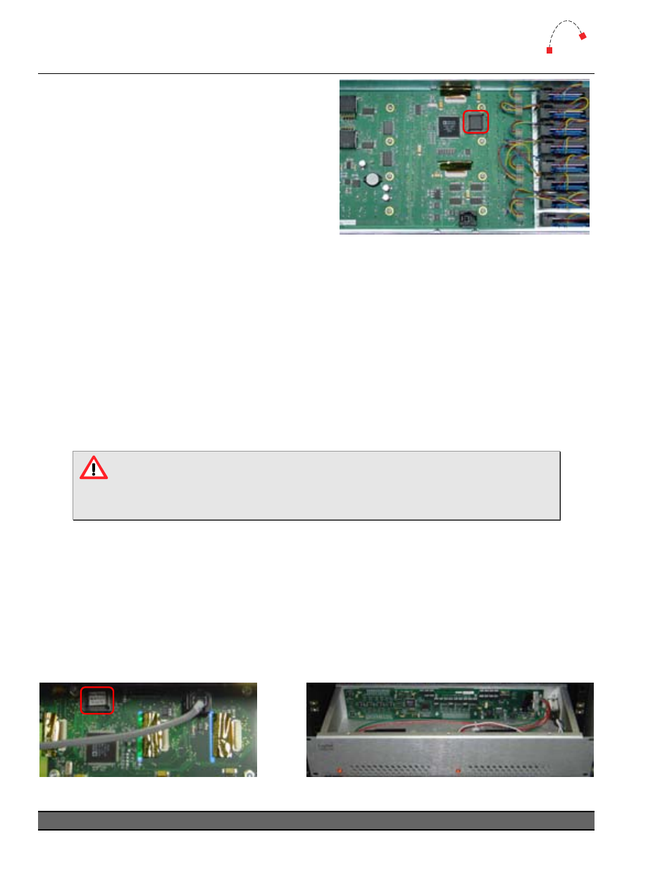
Figure 26 - Master Module underside
1. Remove the two, four or eight hex screws from the required module.
2. Carefully remove the module from the frame.
3. Disconnect the COM cable from the RJ-11 connector.
4. Use the PLCC extractor to carefully remove the existing ROM chip. Depending on the
extractor used, you may only be able to use one side of the tool – if so, exercise caution so
the pins are not bent.
5. Insert the new ROM chip by aligning the notched corner of the chip with the notched
corner of the socket and gently pressing it in.
6. Reconnect the module COM cable.
7. Replace the module in the frame, and screw it back in.
Anti-static precautions should be taken when replacing firmware chips.
In addition, care should be taken with the module components to ensure no
damage is done.
In addition to the module strips, the Power Supply Unit and Meter Bridge also contain a ROM
chip. The replacement procedure is the same, except for the panel removal.
¾
The Power Supply Unit ROM is accessed by removing the top lid of the box. To prevent
damage and because this unit contains live mains, disconnect from mains before removing
the lid.
¾
The Meter Bridge ROM is accessed by removing the rear panel of the bridge. Take care not
to damage the screws when removing this panel.
Figure 28 - Meter Bridge inside
Figure 27 - PSU inside