Precision Digital PD865 User Manual
Page 19
PD865 Snooper Modbus
Serial Input Meter
Instruction Manual
19
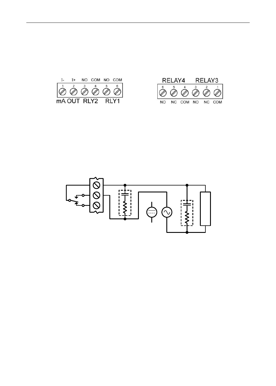
Relay Connections
Connections to the two, standard Form A relays, are made to the
connector labeled RLY1 and RLY2. See Figure 5. Connections to the
two optional Form C relays are made to the six-terminal connector
labeled RELAY3 and RELAY4.
Figure 7: Standard and Optional Relay Connectors
Switching Inductive Loads
The use of suppressors (snubbers) is strongly recommended when switching
inductive loads to prevent disrupting the microprocessor’s operation. The
suppressors also prolong the life of the relay contacts. Suppression can be
obtained with resistor-capacitor (RC) networks assembled by the user or
purchased as complete assemblies. Refer to the following circuits for RC network
assembly and installation:
L
O
A
D
or
Figure 8: AC and DC Loads Protection
Choose R and C as follows:
R: 0.5 to 1
for each volt across the contacts.
C: 0.5 to 1 µF for each amp through closed contacts.
Notes:
1.
Use capacitors rated for 250 VAC.
2.
RC networks may affect load release time of solenoid loads. Check to
confirm proper operation.
3.
Install the RC network at the meter's relay screw terminals. An RC network
may also be installed across the load. Experiment for best results.
4.
For low voltage DC loads, place a diode across the load with a reverse
breakdown voltage two to three times the circuit voltage and a forward
current at least as large as the load current. Shown in
Figure 9